– 10 –
2. DISASSEMBLY
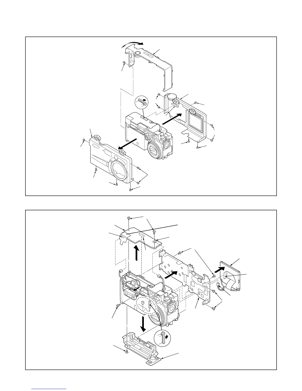
2-1. REMOVAL OF CABINET FRONT, CABINET BACK AND CABINET TOP
2-2. REMOVAL OF SY1 BOARD AND LCD
1. Six screws 1.7 x 2.5
2. Three screws 1.7 x 4
3. Four screws 1.7 x 2
4. Cabinet front
5. Cabinet back
6. FPC
7. Screw 1.7 x 2.5
8. Cabinet top
1. Two screws 1.7 x 3
2. Two connector
3. Connector
4. SY1 board
5. Four screws 1.7 x 3
6. Screw 1.7 x 3
7. Holder card
8. Holder monitor
9. FPC
10. Connector
11. LCD
12. Screw 1.7 x 4
NOTE: Do not touch the holder cabi lock.
Because they change the shape
and get injured.
NOTE: Attach the button buttery + side is
the bottom (Z3001 of SY1 board).
1
1
2
2
1
4
3
3
1
2
1
6
8
7
5
 Loading...