– 12 –
3. ELECTRICAL ADJUSTMENT
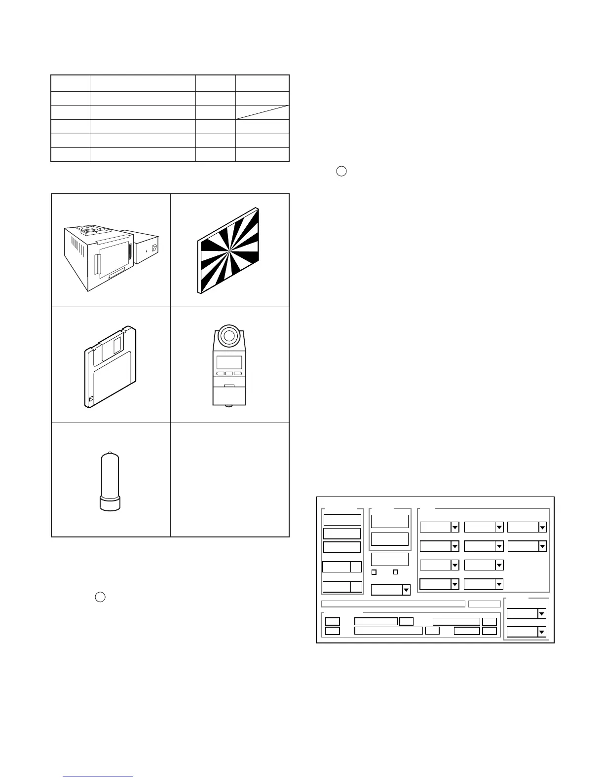
3-1. Table for Servicing Tools
Note: J-1 Pattern box (color viewer) is 100 - 110 VAC only.
3-2. Equipment
1. Oscilloscope
2. Digital voltmeter
3. AC adaptor
4. PC (IBM R -compatible PC, Pentium processor, Window
98 or Me or 2000 or XP)
3-3. Adjustment Items and Order
1. IC501 Oscillation Frequency Adjustment
2. CCD VSUB Adjustment
3. AWB Adjustment
4. Lens Adjustment
5. CCD Defect Detect Adjustment
6. CCD Black Point Defect Detect Adjustment
7. LCD Panel Adjustment
7-1. LCD RGB Offset Adjustment
7-2. LCD Gain Adjustment
Note: If the lens, CCD and board in item 2-6, it is necessary
to adjust again. Item 2-6 adjustments other than these
should be carried out in sequence. For 5 and 6, carry
out adjustment after sufficient charging has taken place.
In case of carrying out adjustment item 3 and 4 after
adjusting item 5 and 6, adjust item 3 and 4 after turing
off the power.
3-4. Setup
1. System requirements
Windows 98 or Me or 2000 or XP
IBM R -compatible PC with pentium processor
CD-ROM drive
3.5-inch high-density diskette drive
USB port
40 MB RAM
Hard disk drive with at least 15 MB available
VGA or SVGA monitor with at least 256-color display
2. Installing calibration software
1. Insert the calibration software installation diskette into your
diskette drive.
2. Open the explorer.
3. Copy the DscCalDI_129 folder on the floppy disk in the FD
drive to a folder on the hard disk.
3. Installing USB driver
Install the USB driver with camera or connection kit for PC.
4. Pattern box (color viewer)
Turn on the switch and wait for 30 minutes for aging to take
place before using Color Pure. It is used after adjusting the
chroma meter (VJ8-0192) adjust color temperature to 3100 ±
20 K and luminosity to 900 ± 20 cd/m
2
. Be careful of handling
the lump and its circumference are high temperature during
use and after power off for a while.
5. Computer screen during adjustment
Ref. No.
Name
Part code
J-1
J-2
J-3
VJ8-0190
VJ8-0193
Pattern box (color viewer)
Siemens star chart
Calibration software
J-4
Number
1
1
1
1Chroma meter
VJ8-0192
1
Spare lump
VJ8-0191
J-5
J-1 J-2
J-3
J-4
J-5
Firmware
Image
AWB
Focus
UV Matrix
RGB Odd
RGB Gain
Tint
RGB Even
VCOMDC
Phase
LCD
Calibration
Upload
Initialize
LCD Type
H AFC Test
VCOMPP(LOW)
VCOMPP(HI)
Cal Data
Cal Mode
OK
OK
EVF
USB storage
Get
Set
VID
Set
PID
Set
Serial
Set
Rev.
Set
Setting
Language
Video Mode
VCO
 Loading...