EasyManua.ls Logo

Sargent and Greenleaf A-Series - User Manual

Sargent and Greenleaf A-Series
43 pages
Print Icon
To Next Page IconTo Next Page
Loading...
A-Series With Display
ACCESS MANAGEMENT SYSTEM
Models 3006-2xx, 3007-2xx, 3028-2xx, and 3029-2xx
Programming and
Operations Guide
The Sargent & Greenleaf A-Series with Display
TM
Locks (models 3006-2xx, 3007-2xx, 3028-2xx, and 3029-2xx) are
designed to provide a high level of security combined with flexible features that allow multiple levels of control over
normal operations and service access. Follow these instructions carefully to get the best possible use from your lock.
For instructions in English, visit the website: www.sargentandgreenleaf.com/ASeriesWithDisplay/
r Anweisungen auf Deutsh besuchen Sie bitte die folgende website: www.sargentandgreenleaf.com/ASeriesWithDisplay/
Pour obtenir les instructions en français, veuillez consulter le site ci-dessous: www.sargentandgreenleaf.com/ASeriesWithDisplay/
Para obtener instrucciones en español, visite la siguiente página web: www.sargentandgreenleaf.com/ASeriesWithDisplay/
Introducti on
It is recommended you run the latest version of Lock Management System (LMS). Running an older version of LMS
may not give you access to all features of lock firmware.
S&G electronic safe locks incorporate sophisticated electronic circuitry. These locks are suitable for indoor use
only.
The keypad should only be cleaned with a soft, dry cloth. Avoid using solvents or liquids.
Never attempt to lubricate the lock or keypad components. Service should only be performed by a qualified
technician.
Anytime the keypad is removed from its mounting base, either disconnect the lock cable or support the keypad
so that it does not hang by the cable. This could adversely affect the cable connector or the keypad receptacle.
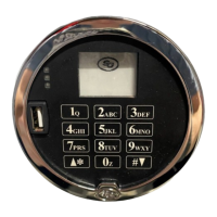
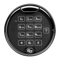
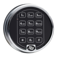
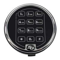
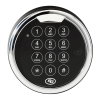
Each time a button is pressed and the lock accepts the input, it will emit a beep, the red LED on the keypad will
flash momentarily, and a * will be displayed on the screen.
All the letters of the English alphabet are displayed on the keypad. This allows you to devise numeric,
alphanumeric, or word-based codes. Use whatever approach works best for you.
All codes end with #. This signals to the lock that you have finished entering all digits of the code.
Personal data directly related to a code holder, such as a birthdate, should not be used in making up a lock code.
Avoid codes that can be easily guessed.
After the lock is changed to a new code, check the lock function by locking and unlocking at least
3 times with the container door open. Make sure the lock functions correctly before closing the door.
The audit features, peripheral devices and accessories, software features, one-time code functionality, USB
functionality, and other additional features are beyond the scope of the UL 2058 standard and are not a part of the
UL Listing.
Sargent & Greenleaf, Inc.
One Security Drive
Nicholasville, KY 40356
Phone: (800)-826-7652 Fax: (800)-634-4843
Phone: (859)-885-9411 Fax: (859)-887-2057
Sargent & Greenleaf S.A.
9, Chemin du
Cr
ose
t
1024 Ecublens, Switzerland
Phone: +41-21 694 34 00
Fax: + 41-21 694 34 09
Copyright 2005-2018 Sargent & Greenleaf, Inc.
Document 630-902
Revised 05/10/2019

Table of Contents

Question and Answer IconNeed help?

Do you have a question about the Sargent and Greenleaf A-Series and is the answer not in the manual?

Overview

The provided document is a programming and operations guide for the Sargent & Greenleaf A-Series with Display™ Electronic Safe Lock and Model 31KP Keypad Limited Warranty. This device is a sophisticated electronic lock system designed for secure containers, offering various operational modes and programming features.

Function Description:

The A-Series with Display™ Lock is an electronic safe lock that allows for secure access control to containers. It supports multiple user types with a hierarchical code structure: Programmer (PIN position 00), Managers (PIN positions 01-03), Supervisors (PIN positions 04-09), and Users (PIN positions 10-29). The lock can be configured into five different user access modes:

  • Multiple User Mode: Any valid code (Supervisor, Manager, or User) can open the lock.
  • Manager/Employee Mode: Managers or Supervisors enable/disable access privileges for individual User Codes. In this mode, Manager and Supervisor Codes do not open the lock.
  • Dual Control Mode: Two independent User Codes are required to open the lock. Manager and Supervisor Codes can also be used in this mode.
  • Day/Night Mode #1: Two independent User Codes are needed to open the lock in "night" mode, while any valid code (Supervisor, Manager, or User) can open it in "day" mode.
  • Day/Night Mode #2: Any valid code (Supervisor, Manager, or User) can open the lock only during the "day" mode (opening window). The lock cannot be opened in "night" mode.

The lock incorporates a time delay feature, which can be programmed from 0 to 99 minutes, with an opening window of 1 to 99 minutes. It also supports Daylight Savings Time (DST) adjustments, allowing for automatic time updates. An optional duress alarm feature can be configured to send a silent alarm to an alarm center. The lock records all activity in an audit trail, storing up to 1,000 events with time and date stamps.

Important Technical Specifications:

  • Attaching Screws: Only provided screws should be used, engaging the mounting plate by at least four full threads. Lock washers or thread sealing compounds are not to be used.
  • Recommended Attaching Screw Torque: 30 to 40 inch-pounds (33.9 to 45.2 dNm).
  • Minimum Lock Cable (Spindle) Hole Diameter: 0.312 inch (7.9 mm).
  • Maximum Lock Cable (Spindle) Hole Diameter: 0.406 inch (10.3 mm).
  • Lock is Designed to Move: 0.0 lbs. (0 Newtons).
  • Lock Bolt Maximum Free Movement: 0.352 inch (8.95 mm); 0.109 inch outside the edge of the lock case.
  • Maximum Bolt End Pressure: Designed to withstand at least 225 lbs. (1000 Newtons).
  • Maximum Bolt Side Pressure: Safe and container boltwork or locking cam designs must never apply more than 225 lbs. (1000 Newtons) of side pressure on the lock bolt.
  • Mounting Environment: The lock body is designed for internal mounting within a secure container, which should offer protection against physical attack. A minimum clearance of 0.150 inch (3.8 mm) is recommended between the end of the lock case and the closest approach of the safe's blocking bar or cam plate.
  • Power: Uses two 9-volt alkaline batteries (Duracell® recommended).
  • Audit Trail Capacity: Stores up to 1,000 events.
  • Code Restrictions: Personal data (birth dates, street numbers, phone numbers) should not be used for lock codes. Easily guessed codes (e.g., 123456, 111111) should be avoided. The factory default code must be changed to a unique, secure code.

Usage Features:

  • PIN Code Entry: Users enter an 8-digit PIN Code followed by the # key.
  • Time Delay: If enabled, users enter their PIN Code to start the time delay, wait for the delay period, and then re-enter their PIN Code during the opening window.
  • Keypad Input Errors: Pressing * twice clears the lock and allows for a restart. A "brap" sound after # indicates an error.
  • Penalty Time: After 5 incorrect codes, the lock enters a 10-minute penalty time, during which no valid code entry is accepted.
  • Lockout (Service Mode): If penalty time is triggered five times in a row, the lock enters lockout mode, requiring a red management key for reset.
  • Bolt Extension Indicator: A double beep (low then high pitch) and a red LED flash indicate the bolt has extended to the locked position.
  • Low Battery Indicator: 5 double beeps and an icon on the screen indicate low batteries. If batteries are too low to open, the lock beeps 20 times.
  • iButton Touch Key: Used to transfer audit trail data to a computer and authorize Service Mode Users.
  • USB Flash Drive: A connector on the keypad allows for audit trail download to a flash drive.

Maintenance Features:

  • Changing Batteries: The lock retains all codes and settings during battery replacement. The keypad housing is pulled away from the door, spring clips release batteries, and new 9-volt alkaline batteries are inserted, observing polarity.
  • Programming Commands: A comprehensive set of commands (e.g., 00* for manual secure mode, 03* for DST time change, 11* for set date, 12* for set time, 13* for start clock, 22* or 33* for changing PIN codes, 28* for audit download, 32* for setting operating mode, 38* for duress alarm, 42* for identifying lock type, 43* for identifying lock mechanics, 44* for identifying operating mode, 45* for initializing the lock, 46* for setting time delay override options, 47* for setting time delay, 48* for setting opening window, 54* for initializing the lock, 55* for enable/disable lock, 56* for manager/employee mode type, 57* for manager/employee mode opening settings, 58* for enable/disable day/night mode, 59* for set opening window for day/night mode, 73* for set date (legacy), 75* for adding code positions, 76* for deleting code positions, 77* for PIN position verification, 78* for set time (legacy), 79* for identifying firmware version, 82* for verifying iButton touch key, 83* for disabling time delay override, 90* for displaying lock serial number, 96* for checking battery level, 97* for displaying current time & date) allow for extensive configuration and management.
  • Audit Trail Download: The audit trail can be downloaded to a USB flash drive using command 28 and then uploaded to a computer with S&G Audit Lock Audit Trail Software or LMS Software. Options are available to download the most recent event, 8, 32, 64, 128, or all up to 1,000 events.
  • Service Mode Operations: Requires a four-digit PIN code and an eight-digit operation code, along with a valid Service touch key. These operations include open lock, program bank features, reset user touch key, reset lockout, revoke dispatcher, add dispatcher, and un-install lock.

Sargent and Greenleaf A-Series Specifications

General IconGeneral
BrandSargent and Greenleaf
ModelA-Series
CategoryLocks
LanguageEnglish

Related product manuals