Do you have a question about the Sartorius CISL1U and is the answer not in the manual?
Safety precautions and general guidelines for working with Combics scales.
Lists necessary special tools and equipment for servicing the Combics scale.
Details the role and operation of the menu access switch.
Explains the function of the SBI/BPI key for communication modes.
Step-by-step instructions for entering BPI mode.
Details on entering the nominal capacity of load cells.
Details standard and trade configurations for A/D converter.
How to adjust the weighing platform for off-center load.
| Calibration | External |
|---|---|
| Interface | RS232 |
| Operating Temperature | +10°C to +30°C |
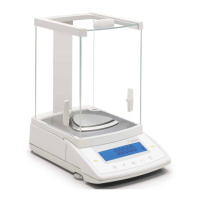
| Pan Size | Ø 120 mm |
| Weighing Pan Size | 120 mm diameter |