Installation Instructions
Unpacking the Equipment
§ Please read the enclosed operating
instructions carefully before putting the
scale into operation.
§ After unpacking the equipment, please
check it immediately for any visible
damage.
$ If you detect any damage, proceed as
directed in under “Safety Inspection”
in the chapter entitled “Care and
Maintenance.”
$ It is a good idea to save the box and all
parts of the packaging until you have
successfully installed your equipment.
Only the original packaging provides the
best protection for shipment.
$ Before packing your equipment for ship-
ment, unplug all connected cables to
prevent damage.
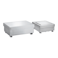
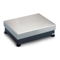
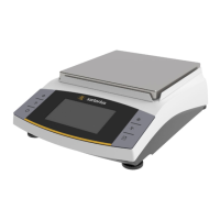
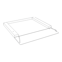
Equipment Supplied
– IF.. weighing platform
– Installation and operating instructions
Requirements for the Place of
Installation
§ Observe all safety instructions.
The IF.. scale is designed to provide
reliable results under normal ambient
conditions. When choosing a location to
set up the IF.., observe the following so
that you will be able to work with added
speed and accuracy:
– Set up the IF.. on a stable, even surface.
The surface directly beneath the scale
should be smooth and dry. The load
that can be carried by the chosen work
surface must be sufficient for both the
weighing platform and any load placed
on the platform. Level the scale using
the built-in level indicator.
When moving the weighing platform, be
sure to observe safety regulations; wear
protective clothing (e.g., hardhat, steel-
toed boots, etc.).
– Avoid placing the equipment in close
proximity to a heater or otherwise
exposing it to heat or direct sunlight.
– Protect the IF.. from direct exposure
to drafts that come from open windows
or doors.
– Avoid exposing the IF.. to excessive
vibration.
– Protect the IF.. from aggressive
chemical vapors.
– Do not expose the equipment to
excessive moisture over long periods.
Turn off the power when the system
is not in use.
– The allowable operating temperature
range is -10°C to +40°C (+14°F to
+104°F).
– If there is any indication that the
equipment does not function properly
(e.g., display remains blank, or no
display backlighting) due to damage
during transport, disconnect the equip-
ment from power and notify your
nearest Sartorius Service Center; see
also: “Safety Inspection” in the chapter
entitled “Care and Maintenance.”
Shock Resistance
Even though the IF.. scales feature
highly rugged construction, there
are some limits. Avoid exposing the
system to falling objects, side impact,
or shocks.
Notes on Integration into Conveyor
Systems
Any moving or rotating parts intended
to be permanently attached to the
IF.. scale must be designed so that they
cannot affect the weighing results.
For example, rotating mechanisms must
be properly balanced.
The IF.. must be clear on all sides during
weighing so that any dirt or parts that
fall will not create a connection between
the weighing platform and any perma-
nently mounted preload components.
Make sure there are no cables or other
objects exerting force on the load plate.
Avoid generating static electricity.
Using the IF...CE in Legal Metrology
in the EU*
The type-approval certificate for veri-
fication applies only to non-automatic
weighing instruments. For automatic
operation with or without auxiliary
measuring devices or equipment, you
must comply with the regulations
applicable to the place of installation.
Conditioning the Weighing System
Moisture in the air can condense on
the surface of a cold weighing instru-
ment or other device whenever it is
brought to a substantially warmer place.
If you transfer the equipment to a
warmer area, make sure to condition it
for about 2 hours at room temperature,
leaving it unplugged from AC power.
Afterwards, if you keep the equipment
connected to AC power, the constant
positive difference in temperature
between the inside of the equipment
and the outside will practically rule out
the effects of moisture condensation.
*
including the Signatories of the Agreement
on the European Economic Area
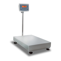
Note:
Connection of the scale to a display
and control unit/indicator, installation,
configuration, and putting the equip-
ment into operation must be performed
by a trained dealer or Sartorius service
representative. Details on additional
settings are contained in the Sartorius
service manual.
– Unplug the power cord from the wall
socket (mains) before performing any
work on the equipment.
– The special tools indicated must be used
when performing installation.
– Installation work that affects the IP65
or IP68 protection rating must be per-
formed with extreme care.
– Any installation work that does not con-
form to the instructions in this manual
will result in forfeiture of all claims
under the manufacturer’s warranty.
– When installing the equipment in
a weighing system, the EU Directive on
Machinery (98/37/EC) must be observed.
– Make sure the junction box and load
cells do not sustain damage.
– Level the scale using the built-in level
indicator.
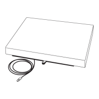
Note:
Make sure there is a faultless connection
between the display and control unit or
indicator and the platform (resistance:
<1 ohm). The shield must be connected
to
the cable gland on the A/D converter
and to the cable gland on the junction
box.
IP Rating
IF.. scales in the galvanized steel version
are rated to IP65; stainless steel versions
have IP68 protection. The levels of pro-
tection indicated by these ratings are as
follows:
First digit: rating 6 indicates that the
equipment is dust-tight; i.e., completely
resistant to penetration by solids. Sec-
ond digit: rating 5 indicates resistance
to penetration by water, including pow-
erful jets of water; rating 8 indicates
resistance to ingress of water during
complete, continuous submersion in
water to a depth of up to 10 meters
(approx. 32 feet).
IP65 or IP68 protection is guaranteed
only if:
– the seals on the junction box are
installed correctly in accordance with
industry standards, and
– the connecting cables, protective caps
and cable glands were installed and
connected by a qualified technician.
4
 Loading...