Edition du 29/03/12 9/16 U508113-e Révision 4
5.4. AB 35 Calibrating mechanism for mechanical indicator
The AB 35 calibrating mechanism is located at the outlet of the transmission device.
The movement of the measuring chamber drives the transmission device gear via the endless screw. At the end
of the transmission device, a drive shaft links to the AB 35 calibrating mechanism.
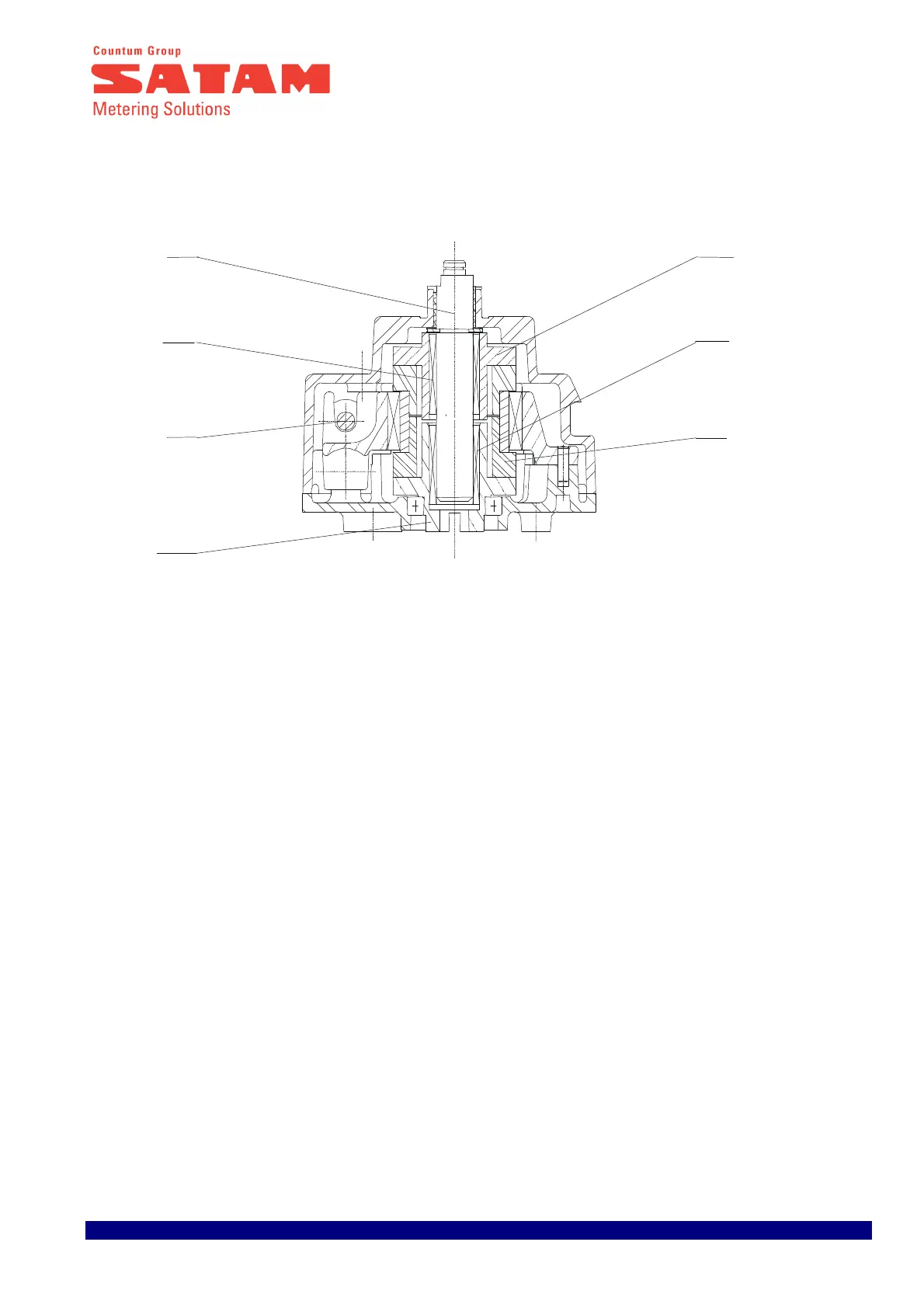
Operation :
Meter movement is transmitted via the inlet shaft (1) to the outlet shaft (2) by a wheel (3). This inlet shaft (1)
drives an eccentric hub (4) which, via the disk (5) and a second wheel (6), drives the outlet shaft (2) faster at
certain parts of the cycle.
The position of the hub (4) can be adjusted using an adjustment screw (7). Each notch of the screw equals a
correction of 0.25‰ , whatever the direction of adjustment. Maximum 40 ‰.
1
7
6
6
3
4
 Loading...