Edition du 29/03/12 13/16 U508113-e Révision 4
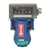
8. Metrological Inspection Measuring Chamber
8.1. General
Current DIRRECTE and LNE (Weights and Measures) legislation require :
. Metrological inspection of meter at operation start-up
. Subsequent yearly inspections.
If during gauging the meter is found to be outside the accepted error, it is possible to re-calibrate the meter using
the AB 35 calibrating mechanism. For meters using an electronic calculator, the re-calibration is made by
adjustment of the calculator correction factor (see annex 2 of document U513237 for the RUBIS, U516318 for the
l’EQUALIS L and U516703 for the EQUALIS MPC).
8.2. Adjustment Procedure for mechanical meter head
A. TEST
1. Carry out a test run at the installation's maximum rate of flow using a 500 litres or 1000 litres gauge.
2. Note the volumes indicated on the Register and on the gauge respectively.
Example : 1000 litres at the Register
997 litres at the Gauge
3. Calculate the difference Register reading – Gauge reading. For the above example :
1000 l - 997 l = 3 l
i.e. a difference of +3 litres for 1000 litres = 3‰
B. PRINCIPLE OF ADJUSTMENT
Reminder : 1 notch of the calibration screw (2) = 0.25‰ in whatever direction adjustment is made.
Maximum : 40‰
1. Note the position of the calibrating screw.
2. Turn the screw the appropriate number of notices in the direction required to obtain the required
adjustment :
Difference (in ‰) / 0.25 = number of notches
In the above example, 3 litres must be added to the gauge. Therefore we must turn the calibration screw (2) in
the direction + :
3 ‰ / 0.25 = 12 notches, in an anticlockwise direction.
 Loading...