A B
DC
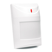
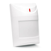
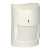
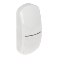
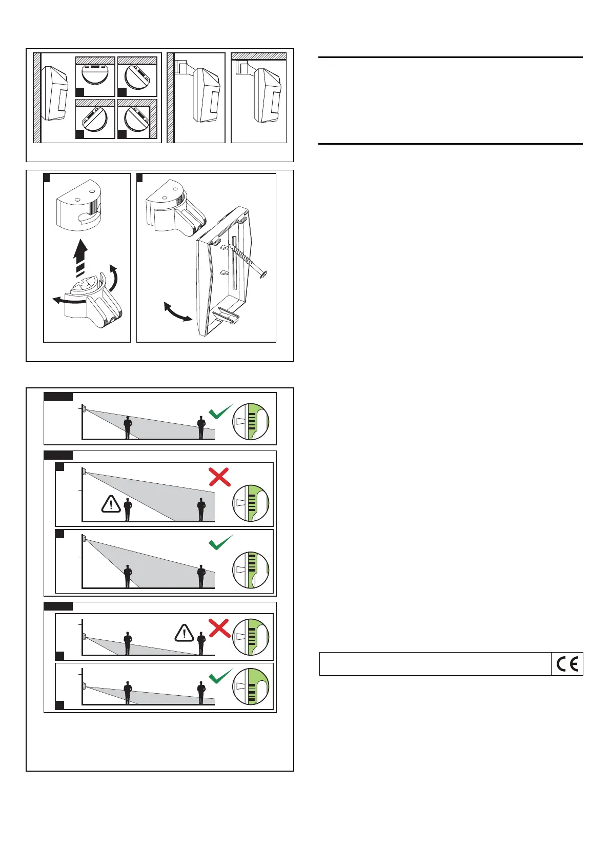
Fig. 5. Ways of installing the detector.
III
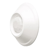
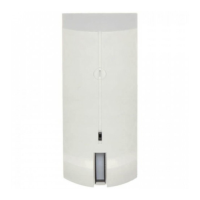
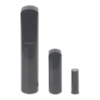
Fig. 6. Mounting the detector on the holder.
6. Fasten the electronics board, taking into consideration the height of detector
installation (see: Fig. 7).
h>2.4 m
B
2.4 m
A
2.4 m
h<2.4 m
C
2.4 m
D
2.4 m
h=2.4 m
2.4 m
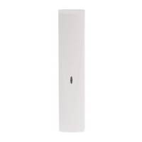
Fig. 7. Effect of the height of installation on the detector coverage area and the
way of positioning the electronics board to optimize the area. Depending on the
mounting height, the medium scale line should be: aligned with the mark on the
enclosure (installation at a height of 2.4 m), situated above the mark (installation
higher than 2.4 m – example B) or below the mark (installation lower than 2.4 m –
example D).
7. Connect the leads to the corresponding terminals.
8. Using jumpers, set the working parameters of the detector.
9. Close the detector housing.
Start-up
1. Switch the detector power on. The LED will start blinking (if the LED ON/OFF
pins are shorted).
2. When the detector enters its working state (the LED will stop blinking), carry
out the detector range test, i.e. check that movement within the supervised
area will activate the alarm relay and lighting of the LED.
3. If necessary, change the detector sensitivity (pins PIR SENS.).
Specifications
Supply voltage................................................................................. 12 V DC ±15%
Current consumption, standby.......................................................................10 mA
Current consumption, maximum....................................................................12 mA
Relay contacts rated load (resistive)............................................. 40 mA / 16 V DC
Alarm signaling time ........................................................................................... 2 s
Detectable speed ................................................................................... 0.3...3 m/s
Security grade according to EN50131-2-2.................................................. Grade 2
Environmental class according to EN50130-5 .......................................................II
Operating temperature range ................................................................-10...+55°C
Standards complied with ........ EN50131-1, EN50131-2-2, EN50130-4, EN50130-5
Dimensions....................................................................................63 x 96 x 49 mm
Recommended installation height................................................................... 2.4 m
Weight .............................................................................................................. 90 g
SATEL sp. z o.o.
ul. Schuberta 79
80-172 Gdańsk
POLAND
tel. + 48 58 320 94 00
info@satel.pl
www.satel.pl
The latest EC declaration of conformity and product approval
certificates are available for downloading on website www.satel.pl
 Loading...