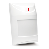
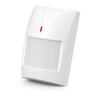
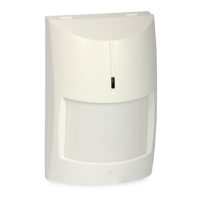
AQUA PLUS
DIGITAL PASSIVE INFRARED DETECTOR
aqua_plus_en 05/09
The microprocessor-based, fully digital AQUA PLUS detector is characterized by
high sensitivity and interference resistance. Due to an advanced digital
temperature compensation feature, the device can work in a wide temperature
range. A dual element pyrosensor is used in the detector. The processor performs
two-way signal analysis, based on value and quantity.
The detector is provided with a prealarm feature. Prealarm is signaled by a short
flash of the LED after changes which do not meet the alarm criteria have been
sensed within the detector coverage area. The prealarm sensitivity depends on
what sensitivity is set on the detector pins. Frequently occurring prealarms may
cause an alarm.
For 30 seconds after the power-up, the detector remains in the starting state,
which is signalized by a rapid LED blinking. Only after this time has elapsed, the
detector will be ready to work.
The detector monitors the supply voltage. If the voltage drops below 9V (±5%) for
more than 2 seconds, the detector will signal a trouble by activation of the alarm
relay and by steady light of the LED indicator. Restoration of a minimum 9V (±5%)
voltage will turn the signaling off.
NC TMP COM
12V
NC TMP
JP1
JP2
JP3
PIR SENS.
LED ON/OFF
1
2
3
4
5
7
6
Fig. 1. View of detector electronics board.
Explanations to Fig. 1:
1 – terminals:
NC – relay (NC)
TMP – tamper contact
COM – common ground
12V – supply input
2 – red color LED to indicate:
– prealarm – short flash (approx. 120 ms);
– alarm – lit up for 2 seconds;
– starting state – blinking rapidly;
– low supply voltage – red light.
3 – pyroelement.
4 – tamper contact.
5 – scale for positioning of pyroelement against the lens (see: Fig. 7).
6 – fixing screw hole.
8 – detector configuration pins:
PIR SENS - setting detector sensitivity (see Fig. 2);
LED ON/OFF - enabling/disabling the LED signaling. The signaling is
enabled when the pins are shorted.
A
JP1
JP2
PIR SENS.
D
JP1
JP2
PIR SENS.
C
JP1
JP2
PIR SENS.
B
JP1
JP2
PIR SENS.
Fig. 2. Setting the detector sensitivity
(A – low sensitivity, B and C – medium sensitivity, D – high sensitivity)
[
– pins shorted; – pins open].
Lenses
An extra wide (EWA) lens is installed in the detector. Optionally, lenses with other
characteristics (coverage patterns) can be purchased and installed.
Name Description Range Angle of view
EWA extra wide angle 15 m 141.2°
LR long range with access
zone monitoring
30 m main beam – 3 m wide (at the
end of range)
VB vertical barrier 22.5 m 2.2 m wide (at the end of range)
Table 1. Available lenses.
0 10 m 20 m
10 m
10 m
0
0
2,4 m
Fig. 3. Coverage area of a detector with EWA type lens.
Note: The detector operating range should be selected to match the size of
space where the detector will be installed. The size of the space along the
main direction of detector positioning is not to be less than 1/3 the nominal
range of the detector. Improper selection of the lens may cause excessive
sensitivity and trigger false alarms.
Installation
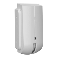
1. Open the housing as shown on Fig. 4.
I II
Fig. 4. Removing the cover.
2. Remove the electronics board.
3. Make suitable openings for screws and cable in the rear panel of the housing.
4. Pass the cable through the prepared opening.
5. Fix the rear housing panel to the wall or to the attached holder.