2 SATEL CA-4v1
Installation of the control panel
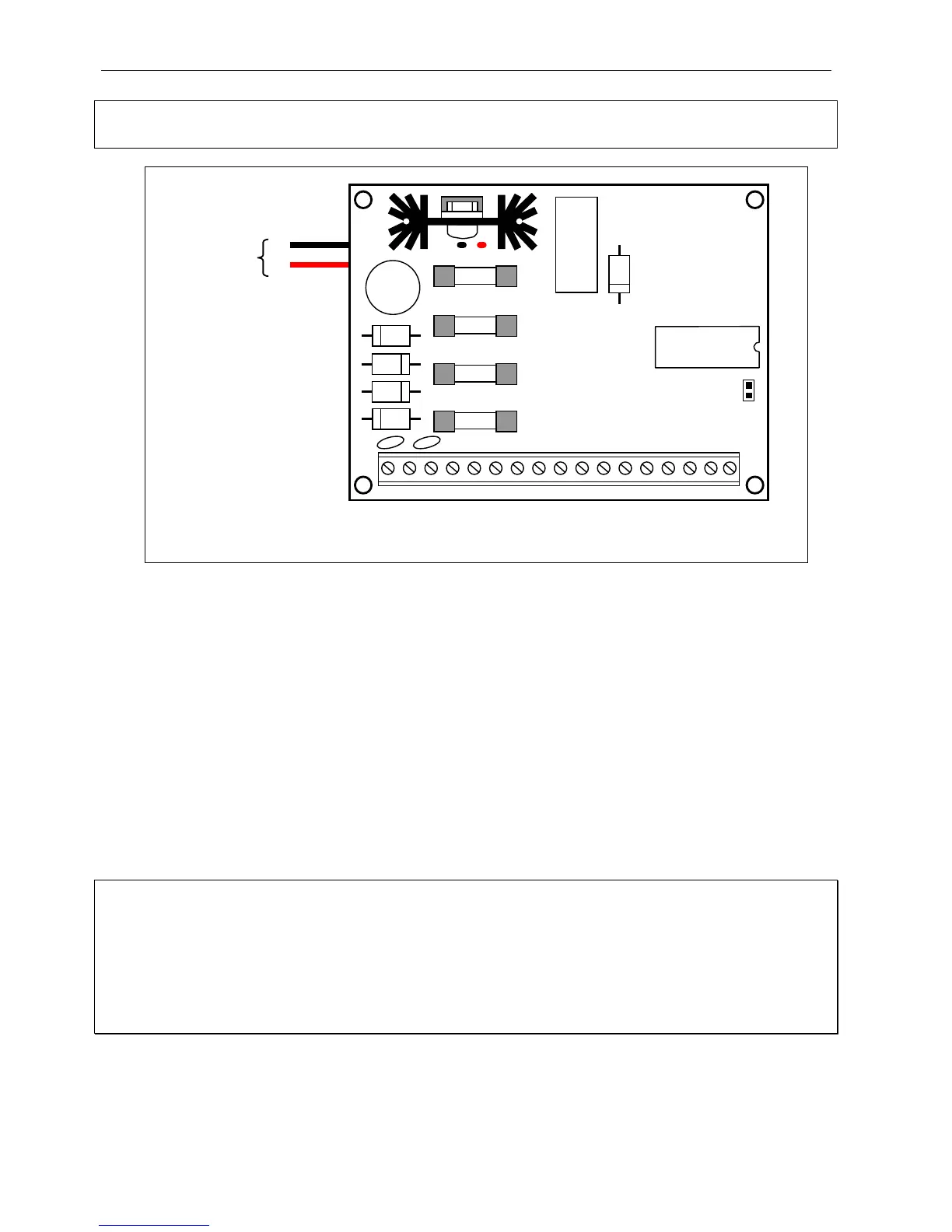
BOARD TERMINALS:
AC
–
module power supply inputs (17...24V AC)
AUX
–
detectors power supply output (+12V DC)
Z1 to Z4
–
zones
OUT1 to OUT2
–
signaling outputs
+KEY
–
keypad power supply output
DATA, CLK
–
keypad bus terminals
COM
–
ground
It is required that the control panel be permanently connected to the mains power. Therefore,
prior to starting the work on the system cabling, make yourself familiar with the electrical
installation of the site and select a circuit which is permanently alive to power the control
panel. The circuit is to be protected with an appropriate fuse.
CAUTION!
The control panel is power supplied from the 230V AC mains. Carelessness or wrong
connection may result in electric shock and pose a threat to life!
Therefore, exercise particular caution when connecting the control panel. In the
process of installation and connection of the control panel, the cable to be used for
mains supply must not be alive!
AC AC AUX +OUT1- +OUT2- COM CLK DATA +KEY Z1 COM Z2 Z3 COM Z4
JP1
RESET
F4
F1
F2
F3
T1A
T3.15A
T1A
T400mA
black
red
BATTERY
-