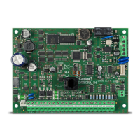
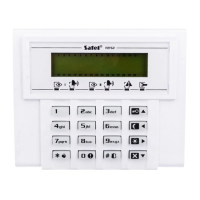
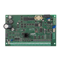
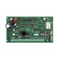
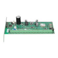
CA-6 SATEL
7
18 - telephone usage status - the output is active when the control panel is on the
telephone line.
19 - ground start - the output is activated by the control panel if the GROUND START
signal is to be generate (a 2 sec. signal occurring before the control panel "lifts the
handset" required by a specific type of telephone exchanges).
20 - monitoring confirmation - the output activated for 3 seconds by the control panel,
after correct termination of the monitoring session.
21 - bypass status - the output is active when some zones are bypassed in the system.
Operation of the output can be limited to showing the bypass of zones specified in
the list of zones, or the bypass of selected partition zones.
22 - READY status - the output is active when all the control panel zones are free from
violations. Operation of the output can be limited to showing the READY status of
zones specified in the list of zones, or the READY status of selected partition.
23 - zone violation - the output starts when one of the zones is violated. Operation of the
output can be limited to the selected "list of zones" or specified partition (identically
as for the 01 output type). The output can remain active for a specified time (from
01 to 99 seconds or from 01 to 99 minutes) or until the armed mode is deactivated
or the alarm cleared.
24 - telephone line trouble - the output used when telephone messaging is doubled by
radio messaging; it makes possible reporting the telephone line trouble.
25 - AC power loss.
26 - battery trouble -
activated when the battery voltage in three consecutive tests drops to
about 11V
.
27 - power supply - the output intended for powering detectors, radio lines and other
equipment with 12V direct voltage. When programming this type of output, pay
special attention to permissible current-carrying capacity of each of the control
panel outputs.
28 - fire detectors power supply - the output intended for powering the fire detectors. The
output closely interacts with the 24H FIRE zones. If assigned to any of the control
panel outputs, it activates the fire alarm verification function. The verification
operates as follows: the first violation cuts the fire detectors power supply off for
about 15 seconds. The power-down results in reset of the violated detectors.
Then, the power supply is restored, but the panel will not control the 24H FIRE
zones for ten to twenty seconds because of the balancing of detectors. Next, the
control panel enters the special mode of fire detectors control, which lasts about
90 seconds. If a repeated detector violation occurs during that time, a FIRE alarm
will be triggered. Otherwise, the control panel will go over to the normal control of
24H FIRE zones (duration of the whole verification process is approx. 2 min.). The
output reacts to the "RESET POWER SUPPLY" function (user function 9).
29 - power supply with RESET function - the output is designated to power detectors
which require a periodical power cut-off until the state memory is cleared. The
RESET function is activated from keypad through the user function 9 (calling:
[CODE][
*
][9]). The voltage is cut off for time programmed as the output active time.
30 - TIMER - the output is controlled by the control panel clock; it is activated / deactivated in
the hours indicated by a corresponding TIMER (see: Functions programming
TIMERS).
31 - audible alarm status - the output signals the audible armed mode. Operation of the
output can be limited to the selected "list of zones" or partition.
32 - full arm status - the output is only active when all zones / partitions assigned to it are in
the armed mode.


 To Next Page