SATEL 3
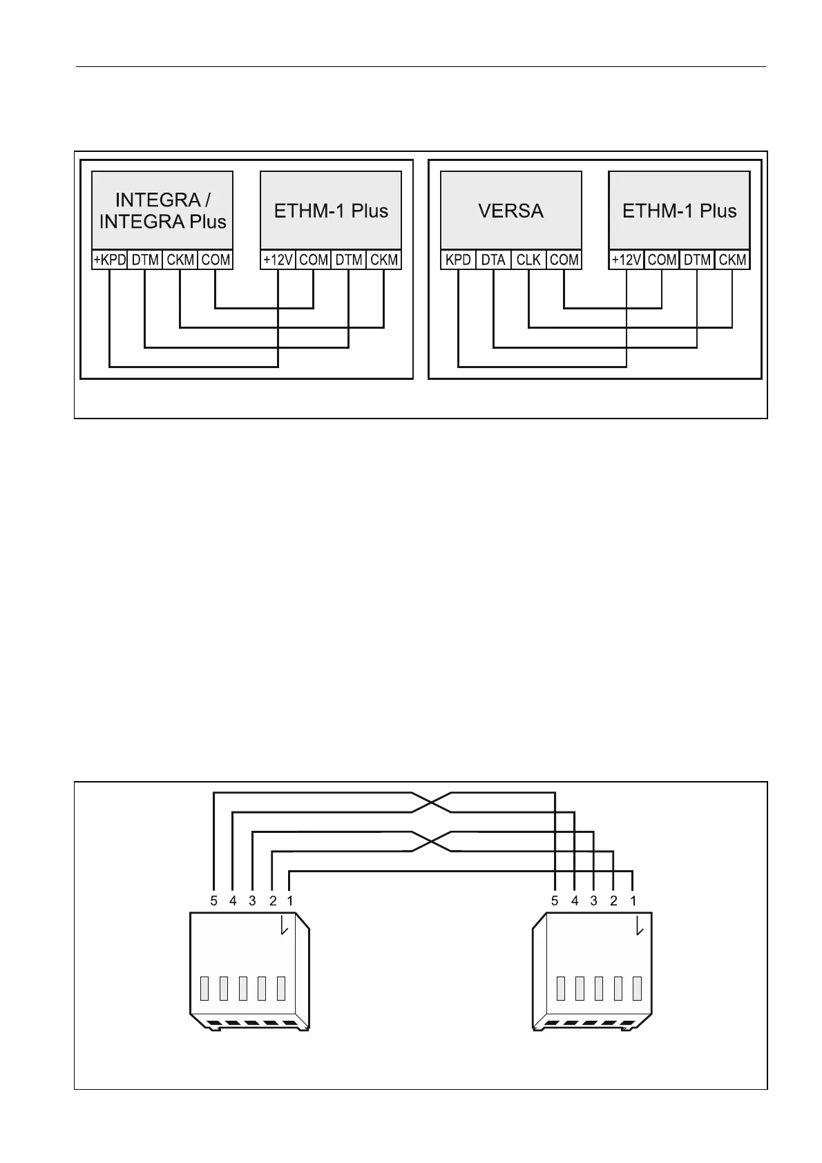
connection. If you use the twisted-pair type of cable, remember that CKM (clock) and
DTM (data) signals must not be sent through one twisted-pair cable. The wires must be
run in one cable.
Fig. 2. Connecting the module to the control panel.
4. If the module is to supervise the enclosure tamper switch, connect the tamper switch
wires to the TMP and COM terminals. Otherwise, connect the TMP terminal to the module
COM terminal.
5. Connect the module to the Ethernet network. Use a cable compliant with the 100Base-TX
standard (identical as for connecting the computer to the network).
6. Power on the alarm system.
7. Start the identification function in the control panel (see the control panel installer
manual). The module will be identified as “ETHM-1”.
8. Configure the module (see full manual).
9. If the control panel is to be configured via the module using the DLOADX program,
connect the module RS-232 port to the control panel RS-232 port. Depending on the
control panel, use the following cable to make the connection:
INTEGRA with connector socket of PIN5 type: PIN5/PIN5 (Fig. 3)
INTEGRA with connector socket of RJ / INTEGRA Plus type: RJ/PIN5 (Fig. 4)
VERSA: PIN5/RJ-TTL
The above mentioned cables are available in SATEL's product offering.
Fig. 3. Wiring diagram of the cable connecting RS-232 ports of ETHM-1 Plus module and
INTEGRA control panel with PIN5 connector socket.
 Loading...