2 PK-01 SATEL
When the code change and service functions are in use, the LEDs are used for
communication with the user.
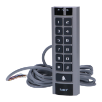
2.2 Keys
The number keys and the and keys are used for entering the code and starting the
functions available in the module and for programming the module.
The key (bell button) controls the OC output of the module. Pressing the bell button
activates the output, which remains on as long as the button is held down.
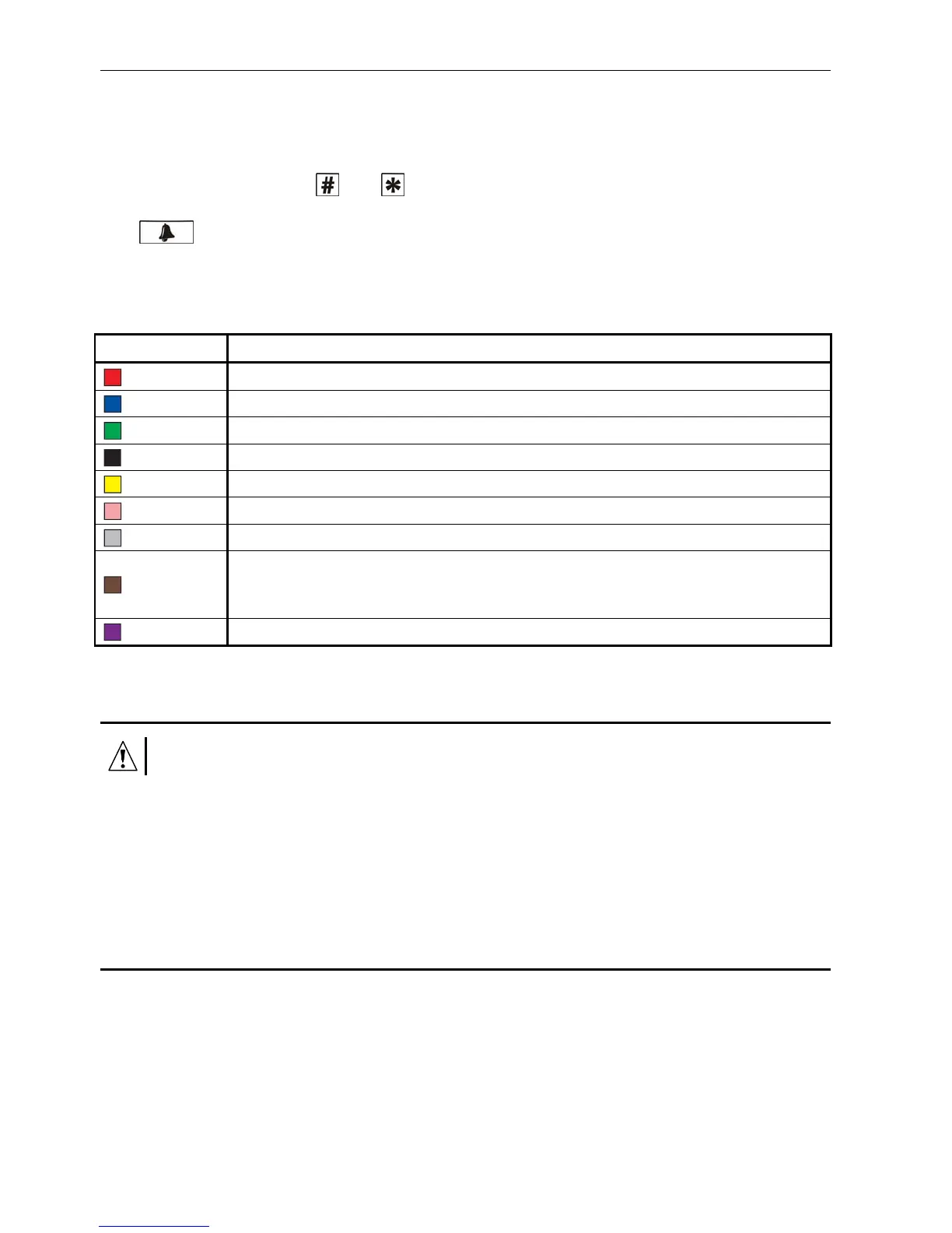
2.3 Wires
Wire color Funcktion
red power supply input (+12 V)
blue common ground (COM)
greek alarm output
black request-to-exit input
yellow NO relay contact (normally isolated from the common relay contact)
pink NC relay contact (normally shorted to the common relay contact)
grey C relay contact (common contact)
brown
door status input (if the door status is not monitored, you will be unable to
unblock / block the door, and the forced entry and long open-door status
will not be signaled)
violet bell output (OC type)
Table 1. Colors and functions of the keypad wires.
3. Installation
Disconnect power before making any electrical connections.
Mounting the module on a metal surface may reduce the working range of the reader, or
even completely disable its operation.
1. Remove the enclosure locking screw and open the enclosure.
2. Secure the enclosure base to the wall.
3. Close the enclosure and replace the enclosure locking screw.
4. Connect individual wires according to Table 1.
4. Users
Users are identified on the basis of their access code or proximity card assigned to them by
the administrator. The access code can consist of 4 to 12 digits.
By default, the administrator (user No. 50) is preprogrammed with the factory code 12345. It
is recommended that you change the code when you first time enter the service mode. The
administrator can use the functions available in the service mode.