IV - USE
Use of the SERVOTOME
®
is restricted to capable
qualified practitioners (dental surgeons) and then
only in a dental surgery.
Prior to initial use:
- Clean, decontaminate and sterilize the accessories
(in particular the electrode-holder and the
electrodes). See section entitled Maintenance:
Sterilization.
- Perform tests on pieces of anatomy (pieces of meat
- ideally, a piece of cow heart, chicken breast,
etc.).
4. 1 MOUNTING THE ELECTRODE
1- Unscrew the electrode-holder cap (21) a few
turns.
2- Insert the appropriate electrode (19) for the
operating procedure.
For the choice of electrode, refer to the
document entitled Servotome® Clinical
Instructions.
Important: Do not use an electrode if its plastic
sheath looks damaged (splits, holes, etc.) or is
missing. Replace the electrode. It is essential to
push the electrode well in so that no metal part
is visible between the electrode-holder cap and
the electrode's plastic sheath (20). Any visible
part would cause the current to flow and result in
a painful incision in the wrong part of the
patient's mouth.
Replace the electrode-holder if it no longer holds
the electrodes tightly.
3- Screw the cap back on again (21).
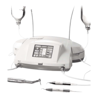
4. 2 START-UP
1- Place the capacitive coupler (5) between the
chair and the patient's back (scapula).
Follow the indication "Patient Side" printed on
the capacitive coupler (22). Check to make sure
the capacitive coupler is in position on the
patient's scapula.
Important: the capacitive coupler does not need
to be in direct contact with the patient's skin. It
is essential that you refer to the section entitled
"Recommendations" before proceeding.
2- Turn the mains switch (16) to the ON position (I).
The green indicator lamp (11) opposite lights up.
The device is on and ready for use.
3- Adjust the incision power ( button, 12) and
coagulation ( button, 13) settings before
operating, to avoid a burn or other undesirable
effect.
Important: It is essential that you refer to the
section entitled "Recommendations" before
proceeding.
11
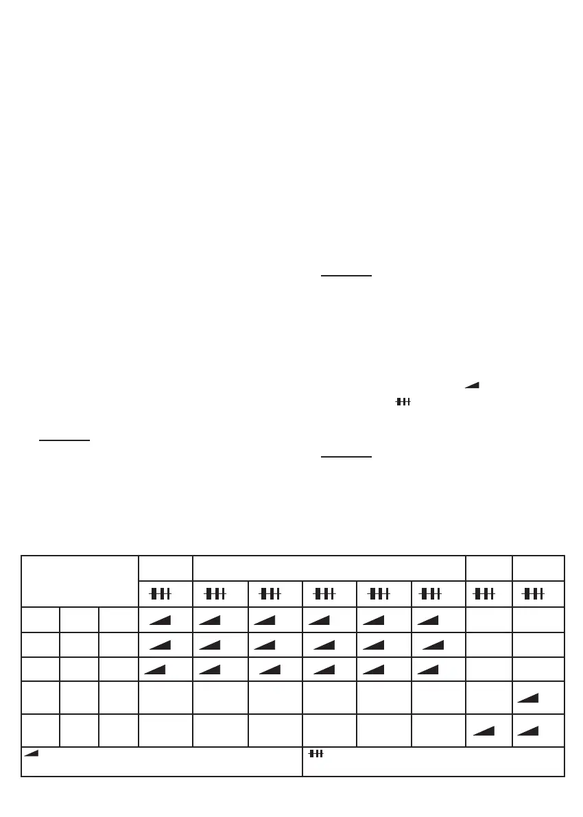
ELECTRODE
SECTION SECTION + MIN. TO MAX. COAGULATION COAG. FULG.
=1 =2 =4 =6 =8 =10 =1 =1
I22S I22CA
=3 =3/4 =3/4 =4/5 =5/6 =5/6
TR22T TR22R TR22L
=4 =4/5 =4/5 =5 =5/6 =6
I40S I40CA
=3/4 =3/4 =4 =4 =5/6 =5/6
FC10N
=5/6
FC25B FC32B
=5 =6/7
= Power (values provided for information only)
= Adjustment of coagulation (values provided for
information only)