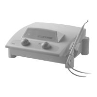
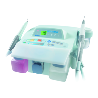
1. 4 FRONT PANEL
This comprises two indicator lamps and two control
buttons.
• "Active" Indicator Lamp (10)
This yellow indicator remains lit as long as the
footswitch is pressed and indicates the presence of
the high-frequency current. Note that a buzzer
sounds while the footswitch is being pressed.
• ON Indicator Lamp (11)
This is green; it lights up when the ON/OFF switch
(16) of the device is ON.
• Button (12)
Minimum to maximum incision power setting. At
maximum power (setting 10), the power delivered is
50W; this does depend, however, on the operating
conditions and the histological variables.
• Button (13)
Coagulation Control:
- Value 1: Minimum coagulation
- Value 10: Maximum coagulation.
1. 5 REAR PANEL
• Capacitive coupler Connector (14)
Connection to the capacitive coupler: please refer to
"Recommendations for use" for the position of the
capacitive coupler.
• Footswitch Connector (15)
Connection to the single footswitch.
• ON/OFF Switch (16)
Position I: ON
• Fuse Housing (17)
Contains the fuses designed to protect the unit.
• Mains Plug (18)
Connection to the mains by a standard plug.
1. 6 SINGLE FOOTSWITCH
Pressing the footswitch (9) activates the high-
frequency output.
1. 7 CAPACITIVE COUPLER
The capacitive (5) capacitive coupler connects to the
device by a lead and returns the high-frequency
current. It should be placed on the clothed patient's
back (scapula).
7