9
1/ START UP
a/ Mains connection (Fig.9)
Connect the cable to the mains network in accordance with local wiring rules.
Identify a protective earth (ground) terminal.
b/ Safety switch connection (Fig.9)
IMPORTANT (EU): The high level safety switch comes with a dry contact rated NC at 250 V at 2 A inductive and 5 A resistive.
IMPORTANT (USA): High level safety switch comes with dry contact NC to be connected only to class 2 circuit not to exceed 42V
peak.
For a NC conguration (Fig.9), we recommend to use this contact to cutout the application, preventing condensate overow.
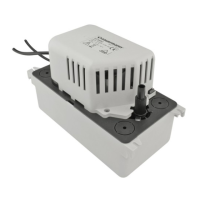
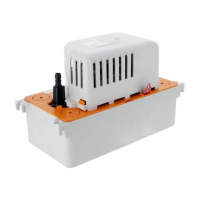
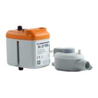
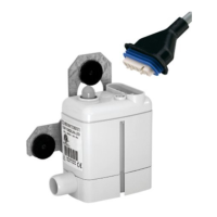
c/ Hydraulic connection (Fig.6-7-8)
The pump unit should be installed horizontally, where the condensate drain pipe can enter into one of the 4 Ø30 mm (1 3/16’’)
inlet holes at the top end of the pump or one side (see g 6). The discharge connection is made through the check valve, to which
a tube of Ø int.10 mm (Ø 3/8’’) should be xed. For Ø int. 6 mm (Ø1/4’’) pipe, a Ø 6 x Ø 10 mm (1/4’’ x 3/8’’) adaptor can be used.
In this case, the ow will be reduced. The acceptable curvature of the tube’s radius is 60 mm max. (2 3/8’’). To t or dismantle the
valve tube, it is preferable to withdraw the check valve beforehand. Drilling for ACC00940 (Fig.6): drill only on the mark provided
for that purpose on one side of the tank in order to avoid any detection system failure.
Please do not test continuously the pump. In case of too close operating cycles, the motor thermal protection can activate and
disable the pump during about 15 minutes.
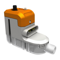
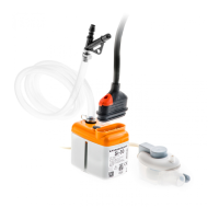
d/ Installation / Settings (Fig.5-8)
The pump can be installed either on the ground, on a wall (xing screws provided) or hanging from the ceiling, using the xed slot
holes on the casing (to hang the pump from the ceiling it is necessary to use two threaded ro + nuts). It is possible to choose the
side of the water exit. To ensure proper ventilation of the motor, the pump must be free of any obstruction. Be careful not to bend
the exible discharge tubing. A reinforced tube can be used. For the reduction in ow due to pressure loss, consult the ow chart.
When the pump is installed with a boiler (EN12056.1, §4.5, §5.8) : discharge tubing must be resistant to acidic water (pH<6.5). Internal
discharge recommended, to avoid freezing pipes.
2/ USE
a/ Operation
Pour water into the pump. Check that the pump starts and stops once the water level begins to fall. To check the safety switch
operation, continue to pour water into the pump until the safety switch is set OFF (use a testing meter).
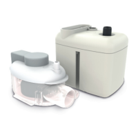
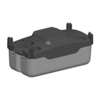
b/ Cleaning
The pump must be disconnected from the mains power supply before any maintenance work is carried out. The inside of the
pump should be cleaned regularly. Remove the tank and clean it with a mild cleaning solution such as water with 5% bleach (see
g 10, the upper part can remain attached to the wall during this operation). At the same time, check that the oat is clean and
free to move. Re-install the tank and re-check the operation (§ 2.a), including the start, stop and safety switch. We recommend
to clean the tank every 6 months.
3/ WARRANTY
2 years : https://sauermanngroup.com/en-INT/warranty
EN
EN
 Loading...