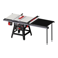
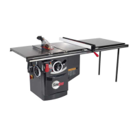
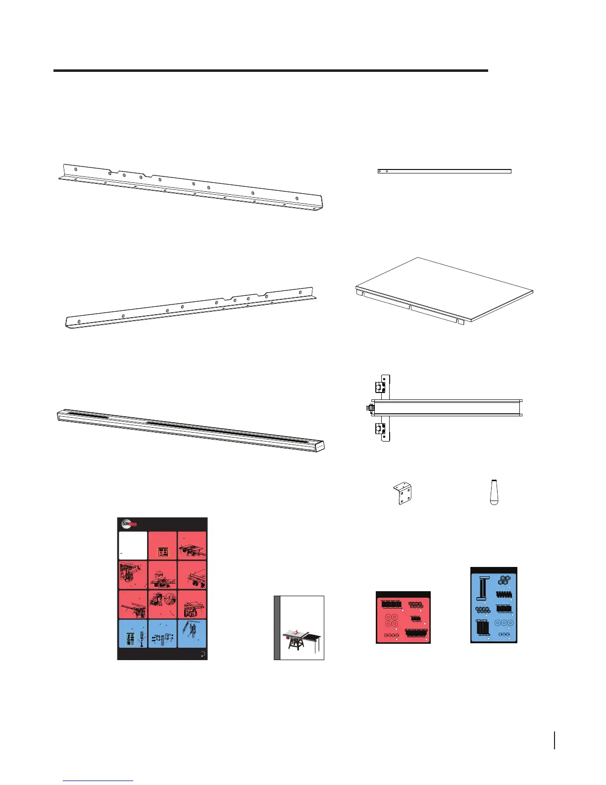
Unpacking Your T-Glide Fence System
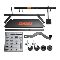
While unpacking your saw, verify that you have all the components shown below for your specic fence
system. The T-Glide Fence System – Professional Series is available in either a 52” system or a 36” system. The
components pictured below are from the 52” system, although the components from the 36” system are similar.
front tube
front rail
rear rail
extension table
installation instructions poster
owner’s manual
SawStop
®
OWNER’S MANUAL
T-Glide
TM
Fence System-
Professional Series
(four for 52” system,
two for 36” system)
angle bracket
fence handle
T-Glide table
hardware pack
18
Countersunk Socket
Head Bolts, M8 x 25 (6)
Washers,
M8.5 x 23 (6)
19
Lock Washers,
M8 (6)
20
Philips Head Screws,
M4 x 16 (12)
17
Foot,
(2)
13
Hex Head Bolts,
M10 x 45 (4)
15
Hex Nuts,
M8 (8)
14
Nylon Lock Nuts,
M10 (4)
16
T-Glide 52” Table Hardware Pack
T-Glide rails
hardware pack
T-Glide Rails Hardware Pack
1
Countersunk Socket Head Bolts,
M8 x 25 (8)
Lock Washers,
M8 (8)
3
Hex Nuts,
M8 (8)
4
Hex Head Screws with Attached
Washers, M8 x 16 (9)
6
Washers,
M8.5 x 23 (8)
2
Countersunk Socket
Head Screws, M8 x 16 (4)
5
SawStop
T-Glide fence
Assembling Your T-Glide Fence System
SawStop Service Department
503-682-6222
www.sawstop.com
Before assembling your T-Glide fence system,
make sure that you have all the necessary
components identified on page 1 in the Owner’s
Manual, including the two hardware packs. Call the
SawStop Service Department at 503-682-6222 if
any components are missing. You will also need the
following tools to complete the fence installation:
1. a 5 mm hex key
2. a 13 mm wrench
3. two 17 mm wrenches (or adjustable wrenches)
4. a Phillips head screwdriver
5. a level or straight-edge
Note: The drawings in the installation poster
illustrate the T-Glide rails and extension table for
the 52” system. The instructions for assembling
and using the 36” system are the same.
1
2
3
4
5
6
7
8
9
10
11
Flip to
Other Side
© SawStop, LLC
TM
1
0
15
30
SawStop
10” Contractor Saw
1
2
3
4
SawStop
System Status Codes
Sta
tusRedGrn
¯¯¯
Wet
Wood
Overload Due
T
o
During By
pass
Contact Detected
During Stan
dby
Contact Det
ected
Brak
e
Adjust Posit
ion of
Doors
Close
Access
Key
To “On”
Turn Cartridge
To “Off”
T
urn Star
t Switch
Bypass Mode On
Coasting
Down
Replace Car
tri
dge
Sys
tem Ready
System Initializing
• • • • • •
¯¯
¯
¯¯
¯
• •
• • • •
¯¯
¯
• • • • • •
• • • • • •• • • • • •
• • • • • •
¯¯
¯
• • • • • •
0
15
30
45
SawStop
10” Contractor Saw
5
Made
in Taiwan
SawS
top, LLC
www.s
a
ws
t
o
p.com
TCP
10¨ Contractor Saw
SawStop
®
Model No. CNS 17
5
Serial No. C074012345
E
le
ctrical / Electricidad / Électricité
1
15/230
Volts, 60 Hz
15/7.5 Amps
1 Phase
1.75 HP
3500 RPM
®
c
US
175370
M
o
ving
b
elts and
par
ts
can pinch
, cut or c
rush.
D
o not o
pe
rate with
b
elt gua
r
d op
en.
Made in
Taiwan
SawStop
, L
L
C
www.
saws
to
p.
com
TC
P
10¨ Contractor Saw
SawStop
®
Model N
o. CNS 175
Serial No. C0
74012345
Electrical / Electricidad / É
lectricité
1
15/230 Volts, 60 Hz
15/7.5
Amps
1 Phase
1.75 HP
3500 RPM
®
c
US
1
753
7
0
Mo
ving
b
elts and parts
can pinch, cut or crush.
Do not o
p
erate with
b
elt guard open.
1
2
3
4
1
SawStop,
the
SawStop
blade
logo,
and the
configur
ation
of
t
his
product
are either
registered
tradema
rks or
trademarks of
SawStop,
LLC.
Softwa
re copyright
2
0
03-2006
by
SawStop,
LLC.
All
rights
reserved.
Protected
by
one
or
more
of
the
foll
owing
U.S.
patents
6813983,
6826988,
6857345
, 6877410,
6880440,
6920814, 6945148,
6945149
, 6957601,
6994004,
6997090,
7000514,
7024975
,
7055417,
7077039, 7098800,
7100483,
7137326
,
7171879,
7197969,
721
0
383, 7225712,
7228772
, 7231856
and T
aiwan
patent 143466.
Additio
nal U.S. an
d foreign patents pending.
!
WARNING
Do
not
remove
the dust shroud
because
the blade
will be exposed.
If
you conta
ct the
blade
under the
table, the blade
ma
y
retract
toward
you
and cause
a
severe injur
y
.
13
14
15
16
17
front rail
level the top of
the front rail with
the lower edge
• Locate the front rail, the rear rail, and the T-Glide rails hardware
pack. All of the hardware needed to install the rails is located on
the T-Glide rails hardware pack and is shipped in the T-Glide
fence box. In order to easily identify the hardware used in each
of the following steps, the different pieces of hardware are
numbered on the hardware pack and in the figures.
• Align the front rail (the larger of the two rails) with the front edge
of the table top so the cut-outs at the top of the rail are centered
on the miter gauge slots in the table and so the holes in the rail
align with the holes along the front edge of the table and
extension wings. Remove six M8 x 25 countersunk socket
head bolts from the T-Glide rails hardware pack and insert
one through each of the holes in the rail and table.
1
• Place an M8.5 x 23 washer and an M8 lock washer
on the back of each of the six M8 x 25 countersunk
socket head bolts , and then thread an M8 hex nut on
each bolt. Hand tighten the nuts; do not fully tighten them.
2 3
1
4
• The holes in the front edge of the table and extension wings are
slightly larger than the bolts they receive to allow you to level the
front rail and extension wings to the table top. Align the top of
the front rail with the lower edge of the bevel on the front edge
of the table top. Use a 5 mm hex key and a 13 mm wrench to
fully tighten the nuts on the back of the four bolts that extend
through the table top. Do not tighten the nuts on the bolts that
extend through the extension wings.
level the extension
wing and tighten the
nut on this bolt
• Use a straight-edge to level the front edge of the left extension
wing to the cast iron table top. You may have to pull up or push
down on the outer edge of the extension wing to level it. Once
the front edge of the left extension wing is level, use a 5 mm hex
key and a 13 mm wrench to fully tighten the nut on the bolt that
mounts the left extension wing to the front rail. Repeat this
process to level the front edge of the right extension wing.
• Align the rear rail (the smaller of the two rails) with the rear
edge of the table top so the cut-outs at the top of the rail are
centered on the miter gauge slots in the table and so the holes
in the rail align with the holes along the back edge of the table
and extension wings. Notice that the holes in the table are
threaded but the holes in the extension wings are not. Remove
four M8 x 16 countersunk socket head screws from the
T-Glide rails hardware pack and thread one through each of the
holes in the rail and into the threaded holes in the table.
Tighten the four screws using a 5 mm hex key.
5
1
• Take two M8 x 25 countersunk socket head bolts and insert
one through each hole in each extension wing. Place an
M8.5 x 23 washer and an M8 lock washer on the
back of each bolt and then thread an M8 hex nut on
each bolt. Hand tighten the nuts; do not fully tighten them.
1
2
3
4
• Use a straight-edge to level the rear edge of the left extension
wing to the cast iron table top. You may have to pull up or push
down on the outer edge of the extension wing to level it. Once
the rear edge of the left extension wing is level, use a 5 mm hex
key and a 13 mm wrench to fully tighten the nut on the bolt that
mounts the left extension wing to the rear rail. Repeat this
process to level the rear edge of the right extension wing.
wing and tighten the
• Once the rails are in place you can mount the extension table to
the rails, but first you must mount the support leg or legs to the
extension table. The extension table for the 36” fence system has
one support leg and the extension table for the 52” fence system
has two. Locate the support legs, the angle brackets, and the
T-Glide table hardware pack. Begin by installing the adjustable
foot in the bottom of each support leg. Thread an M8 nut onto
the threaded shaft of the foot as close to the rubber base as
possible, and then thread the foot into the bottom of the support
leg as far as possible.
14
13
• Each support leg is mounted to the underside of the extension
table using two angle brackets. Align the two holes in the
support leg to the two holes in the brackets. Put one of the
M10 x 45 hex head bolts through each hole in the leg and
brackets. Thread an M10 nylon lock nut on each bolt and
tighten with a 17 mm wrench. You will need to hold the head of
the hex bolt with another 17 mm wrench to tighten the lock nut.
Do not fully tighten the nuts; leave them just loose enough to be
able to move the brackets.
16
15
• Mount the angle brackets to the underside of the extension
table using three M4 x 16 Phillips head screws per bracket.
The underside of the extension table is pre-drilled to receive the
screws. Be careful not to overtighten the screws because you
may strip the threads in the wood. Once all the brackets
have been mounted to the table, fully tighten the
M10 nylon lock nuts that secure the legs to the brackets.
17
T-Glide Rails Hardware Pack
1
Countersunk Socket Head Bolts,
M8 x 25 (8)
Lock Washers,
M8 (8)
3
Hex Nuts,
M8 (8)
4
Hex Head Screws with Attached
Washers, M8 x 16 (9)
6
Washers,
M8.5 x 23 (8)
2
Countersunk Socket
Head Screws, M8 x 16 (4)
5
18
Countersunk Socket
Head Bolts, M8 x 25 (6)
Washers,
M8.5 x 23 (6)
19
Lock Washers,
M8 (6)
20
Philips Head Screws,
M4 x 16 (12)
17
Foot,
(2)
13
Hex Head Bolts,
M10 x 45 (4)
15
Hex Nuts,
M8 (8)
14
Nylon Lock Nuts,
M10 (4)
16
T-Glide 52” Table Hardware Pack
support leg
(two for 52” system,
one for 36” system)
SawStop T-Glide Fence System - Professional Series 1
 Loading...