Operating Instructions Operator and control panel LT 100
3
Date: 19.07.2018
8310068 BA / EN
3 Operation
3.1 Layou t
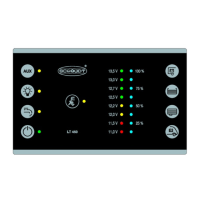
The LT 100 control panel is intended for installation in a cabinet or wall.
2
1
2.1 2.2 2.3 2.4
1.1
1.2
1.3
1.4
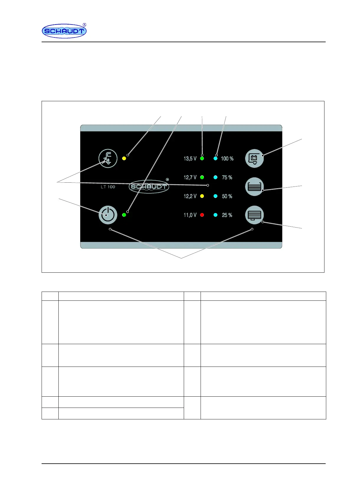
Fig. 2 Layout of L T 100 control panel
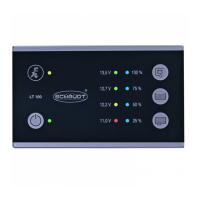
1 Touch sensor 2 Displays
-- -- 2.1
LED mains indicator (yellow):
The LED lights up when mains voltage is pre-
sent at the input of the vehicle mains supply
(also refer to the instruction manual for the
relevant EBL ... / CSV ... power supply in sec-
tion ”Starting up”).
1.1
Main 12V ON/OFF switch:
For switching on and off the 12V supply of the
vehicle
2.2
Indicator LED (green):
Indicates the system is switched on.
1.2 Check of leisure area battery voltage 2.3
4 LEDs (red -- yellow -- green -- green):
Display of the battery voltage in four incre-
ments with voltage information and total di-
scharge warning.
1.3 Check of water tank level
4 LEDs (blue):
1.4 Check of waste water tank level
.
sp
ay o
wa
er an
was
ewa
er
an
eve
s
(four increments).
The LT 100 control panel has touch-sensitive sensors. These sensors react
when touched with a bare finger. The LT 100 control panel cannot detect
touches when gloves are worn (such as for camping in winter). Gloves must
therefore be removed before use.
Gene ra l inform ation
on using
the touch sensors