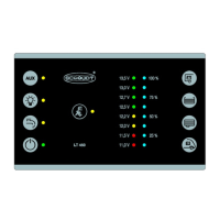
Operating Instructions Operator and control panel LT 100
9
Date: 19.07.2018
8310068 BA / EN
Appendix
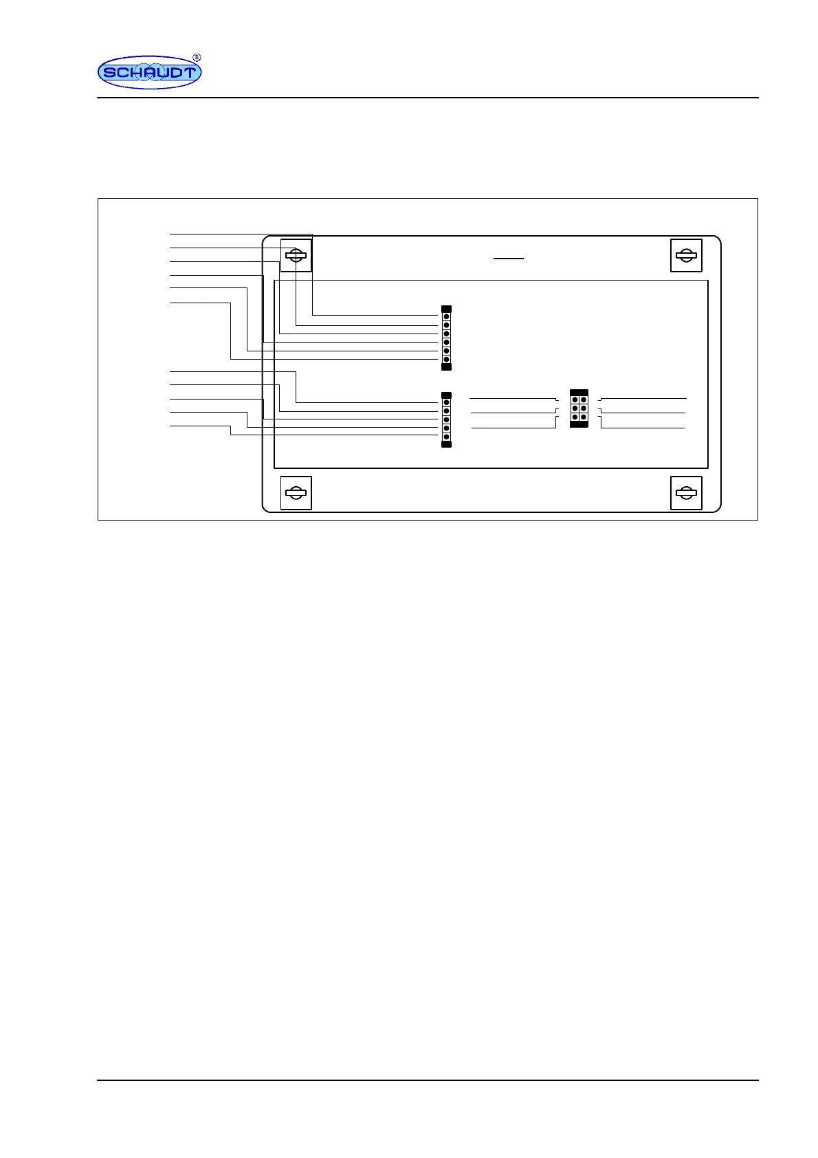
A Block diagram/wiring diag ram
Circuit
board
1
2
3
4
5
6
1
2
3
4
5
1
2
3
4
5
6
Full
3/4
1/2
1/4
Base
n.c.
Full
3/4
1/2
1/4
Base
MicroFit ST2, e.g. Molex 3.0 no. 43645-0600
Rear
Top
MicroFit ST3, e.g. Molex 3.0 no. 43645-0500
MicroFit ST 1
e.g. Molex 3.0 no.
43025-0600
12V OFF
12V ON
12V indicator
W aste water tank
W ater tank
Mains
-- Sensor LAB
+ Sensor LAB
Fig. 3 Wiring diagram for LT 100 control panel
B EC Declaration of Confo rmity
Schaudt GmbH hereby confirms that the design of the LT 100 control panel
complies with relevant regulations.
The original EC declaration of conformity is available for reference at any
time.
Schaudt GmbH, Elektrotechnik & Apparatebau
Planckstraße 8
88677 Markdorf
Germany
Manufacturer
Address