Do you have a question about the Schaudt LT 500 and is the answer not in the manual?
| Brand | Schaudt |
|---|---|
| Model | LT 500 |
| Category | Control Panel |
| Language | English |
Explains the meaning of various safety warning symbols used in the manual.
Outlines essential safety rules regarding regulations, modifications, and qualified personnel.
Warns about permanent damage from prolonged living area battery discharge or overcharging.
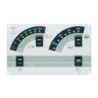
Details the Electrobloc and tank sensors that constitute the control and switch panel system.
Identifies and explains the function of each component and indicator on the LT 500 control panel.
Describes the function of the three switches and the temporary display of indicated values.
States the operating voltage range for the control and switch panel, powered via Electrobloc.
Details how to turn the 12V power supply for the living area on and off using the main switch.
Explains how to switch the 12V pump on/off and the implications for tap usage when off.
Describes the yellow indicator lamp for 230V mains input and its behavior when the engine starts.
Guides users on checking living area battery capacity (%) and charging/discharge current (A).
Explains how to check living area and starter battery voltages and interprets the readings.
Provides a table for interpreting battery voltages for lead gel batteries based on their state and charge condition.
Details measuring off-load voltage to assess battery condition and charging status.
Explains how to view the maximum living area battery capacity in percentage, indicating its health.
Describes how to access and display the software version number of the control and switch panel.
Guides on displaying and adjusting the nominal battery capacity (Ah) for accurate readings.
Monitors battery voltage, shutting down the system to prevent deep discharge.
Details the procedure for checking water and waste water tank levels using the tank level switch.
Explains how to switch the waste water tank heater on and off using the tank level switch.
Covers 'CHARGE!', 'Battery capacity alarm', 'Battery capacity unclear', and 'Mains alarm' indicators.
Explains the '?' warning lamp for tank sensor malfunctions and driving interference with level readings.
Provides instructions for starting the system after battery disconnection, including crucial voltage checks.
Details the process of activating the control and switch panel using the 12V main switch.
Instructions for cleaning the front plate of the control and switch panel safely and effectively.
Steps to electrically isolate the living area battery for storage, protecting it from discharge.
Procedure for fully charging, disconnecting, and storing the living area battery for periods exceeding six months.
A guide to diagnosing and resolving common faults, their causes, and recommended solutions.
Provides contact information, opening hours, and email for Schaudt GmbH technical assistance.
Instructions for sending back faulty units, including packaging and required documentation.
Guidance on the proper disposal of the device according to applicable environmental regulations.
Presents the detailed electrical schematic for the control and switch panel LT 500.
Details the pin configurations and assignments for the main connectors of the control panel.
A template for documenting device defects, including type, version, and specific malfunction details.