Operating instructions Bus System SDTBUS 630 mit EBL 630 B
7
Date:14.12.2018
8110605 BA / EN
3.2.2 Tank module TM 630 B
3
867
5
1 42
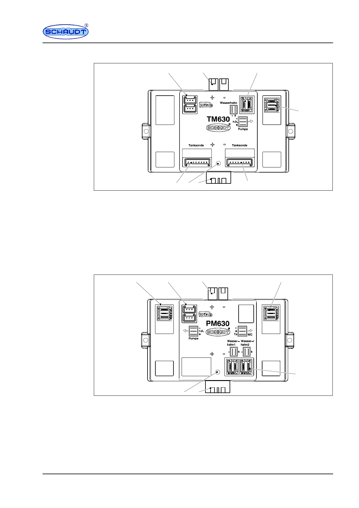
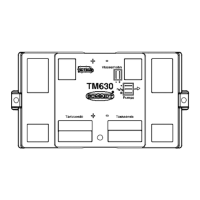
Fig. 5 Layout of TM 630 B tank module
1 Tank probe 1
2 Diagnostics LED
3 Main 12V supply (input)
4 Tank probe 2
5 W ater pump output
6 W ater tap connection
7 Main 12V supply (output)
8SDTBUS 630 connection
3.2.3 Water pump module PM 630 B
2
645
3
1
7
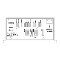
Fig. 6 Layout of the PM 630 B pump module
1 Diagnostics LED
2 Main 12V supply (input)
3 Connectors for water taps 1 and 2
4 Connector for WC pump switch and WC valve
5 Main 12V supply (output)
6SDTBUS 630 connection
7 W ater pump connector



 To Next Page