Do you have a question about the Schaudt EBL 263-5 and is the answer not in the manual?
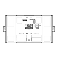
Lists recommended accessories for tank level measurement, including rod tank sensors.
Details physical dimensions, weight, mains supply, battery requirements, and current draw.
Covers essential safety regulations, prohibitions on alterations, and required qualifications for installation.
Explains how to operate the 12V supply, check battery voltage, and provides important cautions.
Describes how LED indicators reflect battery status under different conditions and loads.
Instructions for switching the water pump on/off and notes on its power consumption.
Details control for waste water heater and inquiry of fresh/waste water tank levels.
Explains the function and importance of setting the battery-type selector switch correctly.
Describes the PolySwitch fuses, their function, and troubleshooting for blown fuses.
Explains the operation of main-switch, battery cut-off, and water pump relays.
Details the battery monitor's voltage comparison and automatic shut-down functions.
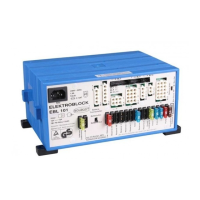
Provides guidelines for transporting, storing, and installing the Elektroblock unit.
Emphasizes qualified personnel, battery connection, and safety precautions for electrical installation.
Details connection procedures for 230V mains supply and battery terminals, including fuse ratings.
Explains connection of 12V consumers and water tanks, and their protection requirements.
Covers initial operation, shutdown procedures, maintenance, and troubleshooting common malfunctions.
Lists enclosures belonging to the manual and delivery requirements.
Certifies compliance with relevant EC low-voltage and EMC directives and applied standards.
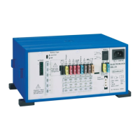
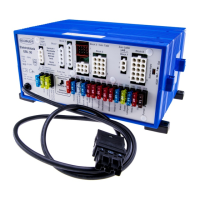
The Schaudt Elektroblock EBL 263-5 is an integrated energy management system designed for motor homes, combining a battery charger, a 12V distribution box, and a control and switch panel into a single unit. Its primary function is to manage the electrical power within the vehicle, ensuring reliable operation of various living-area functions.
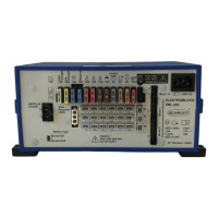
At its core, the EBL 263-5 acts as a central hub for power distribution and charging. It incorporates a charging module (LA 204) that handles battery charging, a battery monitor for tracking battery status, and a comprehensive 12V distribution system with fuse-protected circuits. The unit is designed to work with 6-cell lead-acid or lead-gel batteries with a capacity of 35Ah or more.
The charging system operates with a "IWUoU" characteristic, which includes boost-charge, equalize-charge, and float-charge phases. When connected to a 230V mains supply, it provides a charging current of 10A arithmetic mean or 15A effective at 12.0V charging voltage, with a maximum charging voltage of 14.4V and a float voltage of 13.8V. The system automatically switches between charging phases based on battery voltage. For instance, it enters boost-charge when the battery voltage is below 13.8V. The equalize-charge phase, set at a constant 14.4V, lasts for 20 minutes for lead-acid batteries and 6 hours for lead-gel batteries. If the float voltage cannot be maintained due to high loads, the charger temporarily reverts to boost-charge.
Safety is a key aspect of the EBL 263-5's design. The charging circuits are short-circuit and reverse-polarity protected, requiring a connected battery with a voltage greater than 2.5V to operate. It also includes a 1.6A slow safety fuse in the mains circuit and an over-temperature switch in the transformer to prevent overheating.
When the vehicle is driving, the EBL 263-5 facilitates simultaneous charging of both the starter and living-area batteries via the alternator. A cut-off relay connects the batteries in parallel for this purpose, ensuring the charging current to the living-area battery does not exceed 30A. Additionally, a trickle-charge function provides up to 2A to the starter battery when the EBL is connected to the mains supply.
The integrated battery monitor module plays a crucial role in protecting the living-area battery. It automatically switches off all 12V loads (except the "automatic step" circuit) if the battery voltage drops below approximately 10.5V. This prevents deep discharge, which can damage the battery. Short voltage drops (less than 2 seconds) due to high inrush currents do not trigger this cut-off. If the automatic shut-down is activated due to overload or an insufficiently charged battery, non-essential loads should be switched off. The 12V system can be temporarily reactivated by pressing the 12V push-button switch on the front panel, though it will not switch on if the battery voltage remains below 11.0V.
The EBL 263-5 also manages the power supply to the absorption-type refrigerator, powering it from the starter battery only when the engine is running and a voltage is present on terminal 'D+'.
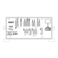
The front panel of the EBL 263-5 serves as the primary interface for controlling and monitoring various living-area functions.
The EBL 263-5 is equipped with PolySwitch fuses for its 12V circuits. These fuses automatically reset after a fault (e.g., overload) is removed, and corresponding LEDs indicate a faulty circuit. In some cases of short circuit, the main fuse of the starter or living-area battery might blow instead of the PolySwitch fuse. Troubleshooting steps involve disconnecting power, identifying the faulty circuit by reconnecting consumer circuits one by one, and then repairing the fault.
The Schaudt Elektroblock EBL 263-5 is designed to be maintenance-free. For cleaning, a soft, moisturized cloth with a mild detergent can be used. It is important to avoid methylated spirit, paint thinner, or similar substances, and to prevent liquids from entering the cabinet.
In case of a malfunction where the charging module needs to charge flat batteries while on mains supply, it is recommended to start the motor home engine for a short period until the battery voltage rises. All connected devices should remain switched off during this process to prevent damage to sensitive devices.
Before and after periods of shut-down (e.g., winter storage), the battery should be fully recharged. This involves connecting the motor home to mains supply and charging the battery for a minimum of 16 hours (for an 80Ah battery) or 24 hours (for a 160Ah battery). For long periods of disuse, the motor home battery should be disconnected from the 12V system by removing the terminals at the battery poles. This prevents battery damage and ensures it remains fully charged.
The device is designed for installation in a dry and sufficiently ventilated environment, within a temperature range of -10°C to +40°C. A minimum distance of 5 cm to surrounding equipment must be maintained on all sides to prevent overheating. The EBL must be fitted on a solid and level surface using the provided fixing holes, ensuring ventilation is not blocked.
| Output Voltage | 12V DC |
|---|---|
| Max Output Current | 25 A |
| Charging Current | 18A |
| Power | 300 W |
| Battery Type | Lead-acid |
| Protection | Overload, short circuit |