www.scheppach.com
GB
|
33
• Relieve the saw band tension if it is not in use for
an extended time, so that it does not become over-
stretched.
m ATTENTION!
break. RISK OF INJURY! If the tension is too low, the
band coming to a standstill.
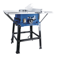
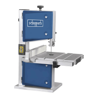
8.7 Adjusting the saw band (Fig. 1 + 1a)
m ATTENTION! Before it is possible to implement the
saw band setting, the saw band must be tensioned cor-
• -
ing mechanisms (12) with the help of the screwdriver
(33).
•
band roller (2). If this is not the case, the angle of the
top saw band roller (2) must be corrected.
• If the Bandsaw blade (26) runs more towards the
rear edge of the saw band roller (2) then the set
screw (17) must be rotated anticlockwise.
• Open the locking screw for the top saw band roller
(16).
•
to check the position of the Bandsaw blade (26).
• If the Bandsaw blade (26) runs more towards the
front edge of the saw band roller (2) then the set
screw (17) must be rotated clockwise.
• After setting the top saw band roller (2), check the
position of the Bandsaw blade (26) on the bottom
saw band roller (8). The Bandsaw blade (26) should
this is not the case, the angle of the top saw band
• Turn the saw band roller a few times, until the ad-
saw band position on the bottom saw band roller (9).
• Tighten the locking screw for the top saw band roller
(16).
•
(13) again and secure with the cover locking mecha-
nisms (12) with the help of the screwdriver (33).
8.8 Adjusting the saw band guide (Fig. 7-10)
Both the support bearing (46 + 52) and the guide pins
change.
• -
ing mechanisms (12) with the help of the screwdriver
(33).
•
sides. The two bolts are used to limit the extension
of the table width enlargement.
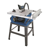
8.3 Fitting the parallel stop (Fig. 5)
•
-
wards.
• When dismantling, pull the clamping lever (42) up-
wards and remove the parallel stop (14).
• The clamping force of the parallel stop can be ad-
8.4 Adjusting the cutting width (Fig. 5 + 5.1)
• The parallel stop (14) must be used when cutting
• Place the parallel stop (14) on the guide rail (43) to
the left or right of the sawing blade
• 2 scales are printed on the guide rail for the parallel
stop (43), which show the distance between the stop
rail and sawing blade.
• -
sion in the window (44) and use the clamping lever
8.5 Using the table width enlargement (Fig. 6-6.2)
• -
• Loosen the clamping lever (10) and pull the table
width enlargement out far enough so that the work-
piece to be sawn can lie on it without tipping.
(Fig. 6.2)
8.6 Tensioning the saw band (Fig. 1)
m ATTENTION! If the saw is at a standstill for an ex-
tended period the saw band tension must be relieved,
the saw blade tension.
• Turn the clamping screw (1) clockwise to tension the
Bandsaw blade (26). The correct tension of the saw
-
the two saw band rollers (2+9). The Bandsaw blade
here.
• -
lic sound when tapped.
 Loading...