www.scheppach.com
36
|
GB
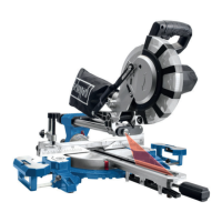
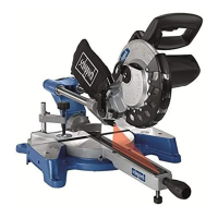
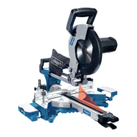
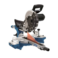
8.6 Mitre cut 0°- 45° and turntable 0° (g. 1/2/11)
The crosscut, drag and mitre saw can be used to make
mitre cuts of 0° - 45° in relation to the work face.
Attention! For mitre cuts (inclined saw head), the left
side of the moveable stop rails (16a) must be xed in
the outer position.
• Open the set screw (16b) for the moveable stop rail
(16a) and push the moveable stop rail (16a) out-
wards.
• The moveable stop rail (16a) must be xed far
enough in front of the innermost position that the dis-
tance between the stop rail (16a) and the saw blade
(6) amounts to a minimum of 8 mm.
• The right side of the moveable stop rails (16a) must
be in the inner positiion.
• Before making a cut, check that the stop rail (16a)
and the saw blade (6) cannot collide.
• Secure the set screw (16b) again.
• Move the machine head (4) to the top position.
• Fix the rotary table (14) in the 0° position.
• Loosen the set screw (22) and use the handle (1) to
angle the machine head (4) to the left, until the poin-
ter (19) indicates the desired angle measurement on
the scale (18).
• Re-tighten the set screw (22).
• Cut as described in section 8.3.
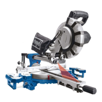
8.7 Mitre cut 0°- 45° and turntable 0°- 45°
(g. 2/4/12)
The crosscut, drag and mitre saw can be used to make
mitre cuts to the left of 0°- 45° in relation to the work
face and, at the same time, 0° - 45° to the left or 0° - 45°
to the right in relation to the stop rail (double mitre cut).
Attention! For mitre cuts (inclined saw head), the left
side of the moveable stop rails (16a) must be xed in
the outer position.
• Open the set screw (16b) for the moveable stop rail
(16a) and push the moveable stop rail (16a) out-
wards.
• The moveable stop rail (16a) must be xed far
enough in front of the innermost position that the dis-
tance between the stop rail (16a) and the saw blade
(6) amounts to a minimum of 8 mm.
• Before making a cut, check that the stop rail (16a)
and the saw blade (6) cannot collide.
• Re-tighten the set screw (16b).
• Move the machine head (4) to its upper position.
• Release the rotary table (14) by loosening the hand-
le (11).
• Using the handle (11), set the rotary table (14) to the
desired angle (refer also to point 8.4 in this regard).
• The moveable stop rail (16a) must be xed far
enough in front of the innermost position that the dis-
tance between the stop rail (16a) and the saw blade
(6) amounts to a minimum of 8 mm.
• Before making the cut, check that the stop rail (16a)
and the saw blade (6) cannot collide.
• Secure the set screw (16b) again.
• Loosen the handle (11) if tightened, pull up the lat-
ched position lever (35) with your index nger and
use the handle (11) to set the rotary table (14) to the
desired angle.
• The pointer (12) on the rotary table must match the
desired angle on the scale (13) on the xed saw ta-
ble (15).
• Re-tighten the handle (11) to secure the rotary table
(14).
• Cut as described under section 8.3.
8.5 Precision adjustment of the stop for mitre cut
45° (g. 1/2/5/9/10)
• No stop angle included.
• Lower the machine head (4) and secure it using the
locking bolt (23).
• Fix the rotary table (14) in the 0° position.
Attention! For mitre cuts (inclined saw head), the left
side of the moveable stop rails (16a) must be xed in
the outer position.
• Open the set screw (16b) for the moveable stop rail
(16a) and push the moveable stop rail (16a) out-
wards.
• The moveable stop rail (16a) must be xed far
enough in front of the innermost position that the dis-
tance between the stop rail (16a) and the saw blade
(6) amounts to a maximum of 8 mm.
• The right side of the moveable stop rails (16a) must
be in the inner position.
• Before making a cut, check that the stop rail (16a)
and the saw blade (6) cannot collide.
• Loosen the set screw (22) and use the handle (1) to
angle the machine head (4) 45° to the left.
• 45° - position angle stop (B) between the saw blade
(6) and rotary table (14).
• Loosen the lock nut (27a) and adjust the adjustment
screw (27) until the angle between the saw blade (6)
and the rotary table (14) is precisely 45°.
• Re-tighten the lock nut (27a).
• Subsequently check the position of the angle indi-
cator. If necessary, loosen the pointer (19) using a
Philips screwdriver, set to position 45° on the angle
scale (18) and re-tighten the retaining screw.
 Loading...