Operating Instructions for Actuators Type AB with Control Unit
OM-ENGLISH-ABCSC.V1.2-16xx-V2.02-2023.04.27 15 Technical data
15 Technical data
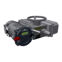
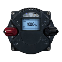
Figure 51: Control unit
Figure 52: Logic-board
15.1 Binary outputs
Count: . . . . . . . . . . . . . . . . . . . . . . . . . . . . . . . . . . . . . . . . . . . . . . . . . . . . . . . . . 8
Power supply: . . . . . . . . . . . . . . . . . . . . . . . . . . . . . . . . . . . . . . . . . . . . . . . . . . 24 VDC nominal
range: 11. . . 35 VDC
(either from internal or external)
Max voltage drop at set output: . . . . . . . . . . . . . . . . . . . . . . . . . . . . . . . . . 1 V
Output voltage at non-set output: . . . . . . . . . . . . . . . . . . . . . . . . . . . . . . . <1 V
Maximum current per output: . . . . . . . . . . . . . . . . . . . . . . . . . . . . . . . . . . . 500 mA (short circuit proof)
Maximum permissible total current for all outputs: . . . . . . . . . . . . . . .4 A
Fuse (Fuse FL2, see Figure 52, page 33): . . . . . . . . . . . . . . . . . . . . . . 4 A slow
(Littelfuse 454 NANO
2
Slo-Blo
®
)
Binary outputs with external supply are separated from other controllers via optocouplers.
It is allowed to connect binary outputs in parallel. If the outputs have the same setting (textitsee Operating
Instructions for SMARTCON Control Units), the current of each output may be added together. If the settings
of the outputs are different, a hardwired logical OR is realized.
15.2 Binary inputs
Count: . . . . . . . . . . . . . . . . . . . . . . . . . . . . . . . . . . . . . . . . . . . . . . . . . . . . . . . . . 5
Nominal voltage: . . . . . . . . . . . . . . . . . . . . . . . . . . . . . . . . . . . . . . . . . . . . . . . 24 VDC
towards common ground
Voltage for input set: . . . . . . . . . . . . . . . . . . . . . . . . . . . . . . . . . . . . . . . . . . . >10 V (8.5 V typ.)
Voltage for input not set: . . . . . . . . . . . . . . . . . . . . . . . . . . . . . . . . . . . . . . . .<7 V (8.5 V typ.)
Maximum voltage: . . . . . . . . . . . . . . . . . . . . . . . . . . . . . . . . . . . . . . . . . . . . . .30 VDC
Current consumtion at 24 VDC: . . . . . . . . . . . . . . . . . . . . . . . . . . . . . . . . . 10.5 mA typ.
Binary inputs are separated from other controllers via optocouplers.
33