P515-167
Cylinder Options
Full Size IC (FSIC)
Small Format (SFIC)
Standard Cylinder
See Keyed Levers/Timing
for installation instructions
Strike
Screws (2)
Latch
Strike
Optional Spacer
for 1³⁄₈” Door (2)
Mounting
Screws (2)
Latch
Screws (2)
Inside Spring
Cage
Pin Wrench
Anti-Rotation
Plate
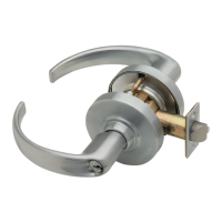
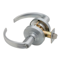
Rose
Outside Lever
Adjustment
Plate
Chassis
Outside
Spring Cage
Inside Lever
ND-Series
Standard Installation Instructions
1
Install Latch
The bevel must face toward the door stop.
Door Preparation
For door preparation use the template included in the package with the lock. For additional information, refer to the Schlage website:
securitytechnologies.ingersollrand.com
2
Install Chassis
IF DOOR THICKNESS IS NOT 1³⁄₄”,
SEE “DOOR THICKNESS ADJUSTMENT”.
Slide Clip
Optional Spacer
1³⁄₈” (35 mm) thick
door ONLY
Latch prongs fi t between slide and slide clip.
Latch
Prongs
Slide
IMPORTANT!
Push latch to center of slide
ND53 Function Shown
3
Non-Keyed Outside Levers ONLY:
Install Outside Lever and Springcage
Keyed IC Outside Levers ONLY:
Install Outside Lever and Springcage - DO NOT
install IC cylinder
Non Keyed Keyed IC
!
IMPORTANT! ALL Keyed Outside Levers:
Follow steps at Keyed Levers/Timing
Non-Keyed Levers ONLY, go to step 4
4
Install Anti-Rotation Plate
Align the tab with the indent
on the hub.
Ta b
Indent
Optional Spacer
1
³⁄₈” (35 mm) door ONLY.
Anti-Rotation
Plate
5
Install Inside Spring Cage Assembly
Lever catch
faces door edge.
Door
edge
6
Install Inside Rose
Rotate rose
until it stops.
Align dimple
and groove.
7
Install Inside Lever
Rotate lever slightly
toward lever catch and
fi rmly push on until lever
catch engages.
Lever catch
8
Install Strike
9
Check Lock Function
If a keyed function does not work properly, see
KEYED LEVERS/TIMING.