*P515-185*
P515-185
© Allegion 2016
Printed in U.S.A.
P515-185 Rev. 02/16-h
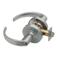
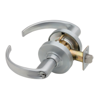
ND-Series Electried Lock
L For standard installation, see full instruction sheet.
Select the appropriate mode for the installation using the mode select switch located on the chassis. Note: When mode is switched (from
EL to EU or EU to EL) the lock requires a complete lock/unlock power cycle to synchronize to the proper mode.
EL, electrically locked (fail safe):
Outside knob/lever or both outside and inside knobs/levers (depending on function) will lock when power is applied. In the event of power failure,
the opening will be unlocked.
EU, electrically unlocked (fail secure):
Outside knob/lever or both outside and inside knobs/levers (depending on function) will unlock when power is applied. In the event of power failure,
the opening will be locked.
Electrical requirements:
The ND-Series electried locks are
powered by DC power only.
DO NOT USE AC POWER.
• Voltage: 12 or 24 V DC (maximum
26.4 V, minimum 10.8 V)
• Holding current: 10 mA
• Peak current: 230 mA
• Operating temperature: 32°F to
120°F (0°C to 49°C)
• All power requirements shown
are for single lock operation.
Troubleshooting:
If lock does not operate –
• Ensure the lock is powered
with DC power.
• Ensure the input voltage is
between 10.8 and 26.4 volts DC.
• Do not use AC power.
Maximum Total Wire Length
AWG 14 16 18 20
Voltage
12 V 500’ (152 m) 300’ (91 m) 200’ (61 m) 100’ (30 m)
24 V Up to 1000’ 304 m
Note: Either lock wire may be attached to either power supply terminal (+ or -).
Switch (not
furnished)
Electried hinge/EPT
(not furnished)
12 or 24 V DC
Lock to hinge/EPT harness
(not furnished)
Power supply
12 or 24 VDC
(not furnished)
Mode
select
switch
Request-to-Exit (RX) Lock
¹³⁄₁₆"
(21 mm)
¹¹⁄₁₆"
(17 mm)
LH or RHR
⁷⁄₈" (22 mm)
drill thru
Latch
2¹⁄₈" (54 mm)
⁵⁄₁₆" (8 mm)
⁵⁄₁₆" (8 mm)
1³⁄₈"
(35 mm)
1³⁄₈"
(35 mm)
C
L
RH or LHR
⁷⁄₈" (22 mm)
drill thru
2⁵⁄₈" (67)
³⁄₄" (19)
³⁄₈"
(10)
¹³⁄₁₆"
(21 mm)
¹¹⁄₁₆"
(17 mm)
Drawing is not to scale.
Door Preparation: Important! Drill RX hole rst.
RX utilizes a microswitch inside the lock case to detect
rotation of the inside knob/lever. The switch then signals
the use of the opening to the security system. Attach
wires from RX switch wire harness to an electried hinge/
EPT (not furnished). Refer to the
Allegion Connect section below
for wire identication.
Electrical rating: 2 A, 30 V DC
Power
RX
Allegion Connect
Allegion Connect, a factory-installed Molex
®
connector system, provides simplied installation and maintenance utilizing quick-connect harnesses and
hinges. Alternatively, the Molex connector may be cut off and the lock installed with traditional wire splicing methods.
WIRE COLOR AND FUNCTION
Pin Color Function
1 Black Power (auto detects GND, +12 or +24 V DC)
1
2
3
5
6
7
8
2
Red
Power (auto detects GND, +12 or +24 V DC)
3 Purple RX NO (normally open)
4 Grey RX NC (normally closed)
5 White RX COM (common for RX)
6, 7, 8 Not used
Variable length wiring
harness (6" to 192")
EPT or electried hinge
6” wiring harness
To
Power
Supply
All installations should be in accordance with local
electrical codes and national electrical code, NFPA 70.
ND-Series Electried Locks
Wiring Instructions and Specications
Customer Service Servicio al cliente Service à la clientèle
1-877-671-7011 www.allegion.com/us