56 • Schlage • ND-Series service manual
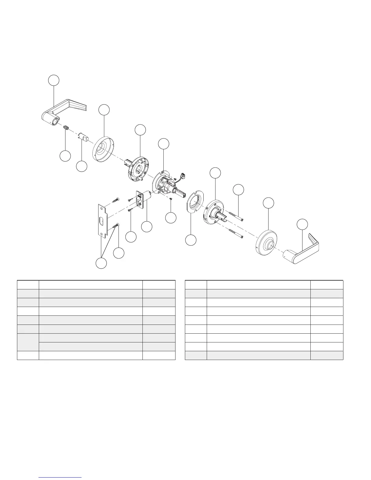
Trim assemblies
Exit lock—electrically locked (fail safe) or electrically unlocked (fail secure)
ND12EL or ND12EU**
A
B
E
H
D
C
K
N
Q
M
CC
DD
P
C
J
GG
Letter Description Part number
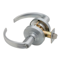
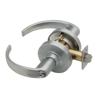
A Outside lever—closed 03-230
B Inside lever—closed 03-230
C Rose 03-042
D Outside spring cage assembly—standard N523-218
E Inside spring cage assembly—standard N523-221
H
Chassis, electrically locked 63-180*
Chassis, electrically unlocked 63-181*
J Anti-rotation plate N523-055
Letter Description Part number
K Deadlatch 13-247
M Strike assembly 10-025
N Latch screw C603-897
P Mounting screw N523-021
Q Strike screw C603-256
CC Spring, plunger C503-331
DD Catch stop N523-041
GG Adjustment plate screws N523-240
* Chassis part number is for reference only.
** For electrified lock details, see Electrified locks on page 105.
Designates new parts or assemblies.