5/12
Fix-EZ™ Installation Manual
MI-018CA
072216
© Schletter Canada Inc.
• 3181 Devon Drive • Windsor, Ontario N8X 4L3 • Tel: (519) 946 – 3800 • Fax: (519) 946 – 3805
E-mail: mail@schletter.ca • www.schletter.ca
A. Portrait
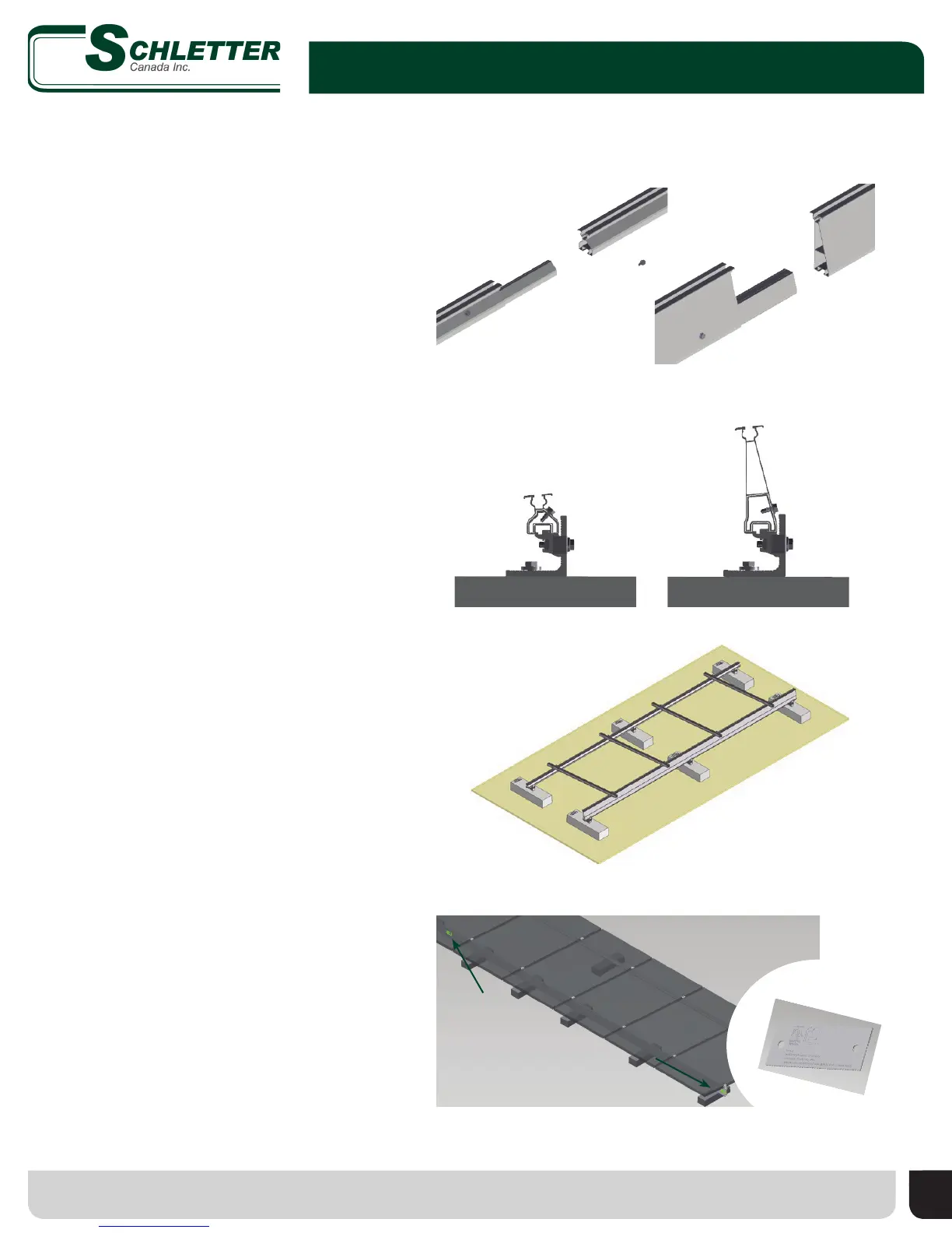
• If project calls for splices, connect front
and rear rails with provided splice kits
which include necessary hardware.
• To connect rail lengths to assembled
ballast block and L-foot connection,
simply position rail groove over protrusion
of KlickTop
™
and press into place, tighten
Torx
®
screw.
• Repeat for all front and rear rails.
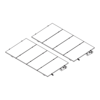
4. Connect Module Support Rails (Portrait)
• Install front and rear rails.
• Attach KlickTop mounting clamp to front
and rear rail in locations specied in
system specic drawing.
• Align cross rail and hook bottom channel
onto KlickTop.
• Repeat for all cross rails until end
of row.
• See page 9 for re
barrier installation
Insert portion of internal splice into one rail, insert exposed end of splice into second
rail and secure with one self-drilling screw per side
Position bottom of rail over KlickTop and press into place, tighten Torx screw
Attach KlickTop to front and rear rail; slide bottom of cross rail onto KlickTop;
tighten bolt to secure cross rail
B. Landscape
4. Connect Module Support Rails and Cross
Rails (Landscape)
5. Listing Requirement
Attach labels to rails using self-drilling screws
• IMPORTANT! Listing requires one label be
placed every 18 feet on all rear rails.