1/12
Fix-EZ™ Installation Manual
MI-018CA
072216
© Schletter Canada Inc.
• 3181 Devon Drive • Windsor, Ontario N8X 4L3 • Tel: (519) 946 – 3800 • Fax: (519) 946 – 3805
E-mail: mail@schletter.ca • www.schletter.ca
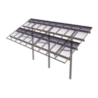
Fix-EZ
Designed for at roof applications, the multifunction Fix-EZ solar mounting system mounts solar photovoltaic (PV) modules on
roof tops with minimal load and materials, thereby reducing installation time and costs. The Fix-EZ is specically designed to meet
or exceed applicable IBC, ASCE, and UL standards.
Features
• Conforms to UL 2703
1
• Certied to ULC/ORD Std C1703
• Fire class resistance rating: Class A when used with
Type I or Type II photovoltaic modules in landscape orientation only
2
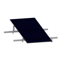
• Multiple module tilt options available
3
• Portrait or landscape module orientation
4
• Ballast block included
• Includes Rapid5K
TM
grounding module clamps
• Wind tunnel tested
• Optional wire management
• 30 Amp fuse series rating
Provided as a complete mounting system, the Fix-EZ includes several multifunction components to maximize functionality and
minimize cost. Ballast blocks act as ballast weight as well as system support. Module mounting rails support modules⁵ and act as
windbreak with Rapid5K™ module clamps securely holding modules in place while bonding/grounding them to the system. The
following is a guide to properly install a Fix-EZ in order to meet design and test standards.
6
1
The Fix-EZ is evaluated for electrical bonding only. The Fix-EZ meets all IBC and ASCE requirements for structural loading; it was not evaluated for loading under UL 2703.
2
Special consideration needs to be taken during design phase if system requires protective re barrier.
3
Module tilt will vary depending on module manufacturer’s connection requirements: tilt options range from 7 degrees to 15 degrees
4
Maximum number of modules shall not exceed maximum system voltage.
5
This racking system may be used to ground and/or mount a PV module complying with UL1703 only when the specic module has been evaluated for grounding and/or mounting in
compliance with the included manual
6
Installer is responsible for verifying that photovoltaic system meets applicable NEC standards.
7
Individual parts and components may vary from system-to-system. Please reference system specic drawings.
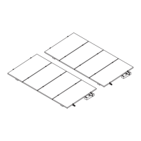
Key Components
7
1. Concrete ballast blocks
2. Adjustable L-foot
3. Module support rails (purlins)
4. Rapid5K
TM
grounding module clamps
1
4
3
3
2