2
Operating instructions
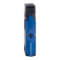
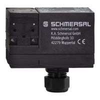
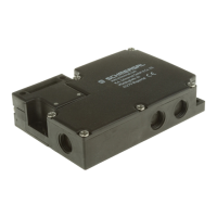
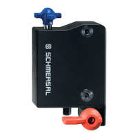
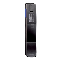
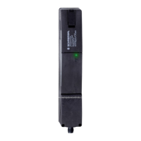
Solenoid interlock
AZM150
EN
1.6 Warning about misuse
In case of improper use or manipulation of the safety
switchgear, personal hazards or damages to machinery or
plant components cannot be excluded.
1.7 Exclusion of liability
We shall accept no liability for damages and malfunctions resulting from
defective mounting or failure to comply with this operating instructions
manual. The manufacturer shall accept no liability for damages resulting
from the use of unauthorised spare parts or accessories.
For safety reasons, invasive work on the device as well as arbitrary
repairs, conversions and modifications to the device are strictly forbidden,
the manufacturer shall accept no liability for damages resulting from
such invasive work, arbitrary repairs, conversions and/or modifications
to the device.
2. Product description
2.1 Ordering code
This operating instructions manual applies to the following types:
AZM150SK-
➀
R
➁➂➃
-
➄
-
➅
No. Option Description
➀
Magnet: Actuator:
02 / 11 2 NC 1 NO / 1 NC
11 / 11 1 NO / 1 NC 1 NO / 1 NC
11 / 02 1 NO / 1 NC 2 NC
02 / 02 2 NC 2 NC
01 / 03 1 NC 3 NC
03 / 01 3 NC 1 NC
01 / 12 1 NC 1 NO / 2 NC
➁
Standard coded (Actuator not included in delivery)
I Individually coded (incl. actuator see
➅
)
➂
Power to unlock
A Power to lock
➃
Manual release
T Emergency Exit
N Emergency release
➄
024 U
s
24 VDC
110 U
s
110 VAC
230 U
s
230 VAC
➅
Including actuator for individually
coded versions I:
B1 Straight actuator B1
B5 Angled actuator B5
B6L Flexible actuator B6, left
B6R Flexible actuator B6, right
Standard coded actuator (not included in delivery)
AZM150-B1 Straight actuator
AZM150-B5 Angled actuator
AZM150-B6 Flexible actuator
AZM150
➀
-
➁
-
➂
R
➃➄➅
-024-
➆
with connector plug M12, 8-pole
(only 24 VDC)
No. Option Description
➀
Z
Guard locking monitored
(Variants 02/.., not in power to lock version)
B Actuator monitoring (Variants ../02)
➁
ST Connector plug M12 bottom
STR Connector plug M12 right
STL Connector plug M12 left
➂
Magnet: Actuator:
10 / 02 1 NO 2 NC
02 / 10 2 NC 1 NO
01 / 02 1 NC 2 NC
02 / 01 2 NC 1 NC
➃
Standard coded (Actuator not included in delivery)
I Individually coded (incl. actuator see
➆
)
➄
Power to unlock
A Power to lock
➅
Manual release
T Emergency Exit
N Emergency release
➆
Including actuator for individually
coded versions I:
B1 Straight actuator B1
B5 Angled actuator B5
B6L Flexible actuator B6, left
B6R Flexible actuator B6, right
Standard coded actuator (not included in delivery)
AZM150-B1 Straight actuator
AZM150-B5 Angled actuator
AZM150-B6 Flexible actuator
Only if the information described in this operating instructions
manual are realised correctly, the safety function and therefore
the compliance with the Machinery Directive is maintained.
2.2 Special versions
For special versions, which are not listed in the ordering code
below 2.1, these specifications apply accordingly, provided that they
correspond to the standard version.
2.3 Purpose
The solenoid interlock has been designed to prevent in conjunction with
the control part of a machine, movable safety guards from being opened
before hazardous conditions have been eliminated. The solenoid
interlocks with individual coding offer a higher protection against
tampering and remain off when the guard system is unlocked or open.
Interlocks with power to lock principle may only be used in
special cases after a thorough evaluation of the accident risk,
since the safety guard can be opened immediately on failure
of the power supply or upon activation of the main switch.
The safety switchgears are classified according to
EN ISO 14119 as type 2 interlocking devices. Designs with
individual coding are classified as highly coded.
The AZM150ST is also for use in combination with the
safety field box SFB made by Schmersal.