7
AZM150
Operating instructions
Solenoid interlock
EN
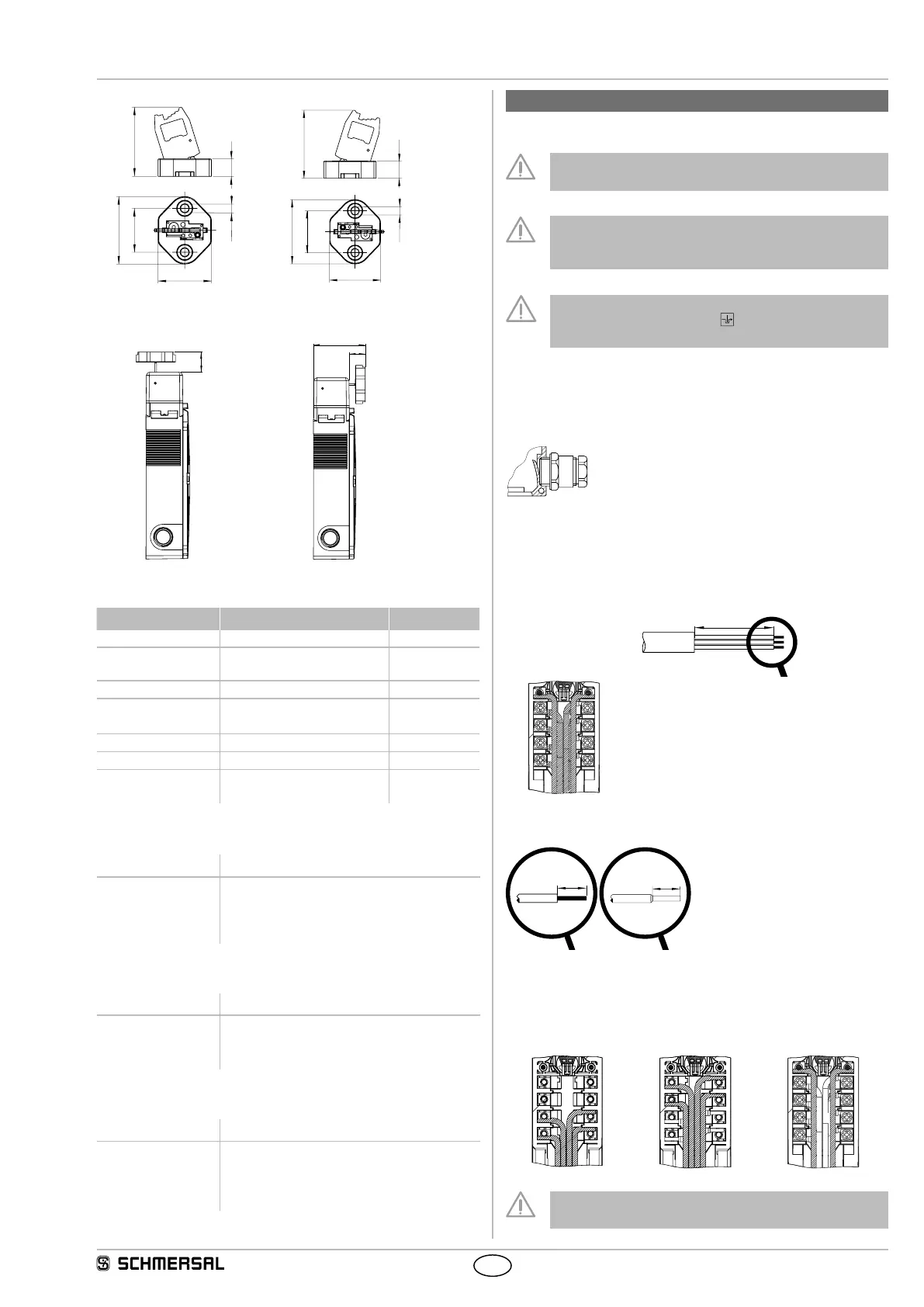
Actuator AZM150-B6L Actuator AZM150-B6R
28
34
43
44
11
ø 5.5
28
34
43
ø 5.5
44
11
Installation position with actuator inserted
(all measurements ± 0.3 mm)
23
18,5
58.8
3.4 Accessories
Description Designation
Ordering code
Mounting plate MP-AZM150-1 153046398
Mounting plate,
angled
MP-AZM150-2-R/L 153046399
Triangular key TK-M5 101100887
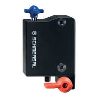
Door handle system DHS-150-BKBU-L
DHS-150-BKBU-R
137000626
137000625
Lockout tag SZ150-1 153027887
Cable gland M20 x 1,5 on request
Tamperproof screws
M5 x 14, 2 pieces
ACC-NRS-M5X14-FHS-2PCS
103033698
Connecting cables with coupling (female)
IP67, M12, 8-pole – 8 x 0.25 mm²
Cable length Ordering code
2.5 m
5.0 m
10.0 m
15.0 m
103011415
103007358
103007359
103011414
Connecting cables with angled coupling (female)
IP67, M12, 8-pole – 8 x 0.25 mm²
Cable length Ordering code
2.5 m
5.0 m
10.0 m
103043110
103043119
103043120
Connecting cables to connect to the safety fieldbox
IP67, M12, 8-pole – 8 x 0.25 mm²
Cable length Ordering code
1.0 m
1.5 m
2.5 m
5.0 m
101217787
101217788
101217789
101217790
4. Electrical connection
4.1 General information for electrical connection
The electrical connection may only be carried out by
authorised personnel in a de-energised condition.
To connect the AZM150 as a connecter variant, a PELV
mains supply device must be used in accordance with
EN 60204-1.
If the risk analysis indicates the use of a monitored interlock,
only contacts marked with the symbol may be integrated
into safety circuit.
Appropriate cable glands with a suitable degree of protection are to
be used. Remove the walls of the mounting holes by inserting the
cable entry. All plastic residues must be removed from the switch
compartment.
After wiring, the wiring compartment must be cleaned (i.e. remove
excess cables etc.).
Max. cable section:
0.25 … 1.5 mm²
(incl. conductor ferrules without plastic collar)
Removing the
cable sheathing
A1 A2
1. 1.
2. 2.
3. 3.
4. 4.
11-
y = 71 mm
y = 67 mm
y = 57 mm
y = 47 mm
y = 37 mm
Settle length x of the conductor: 6 mm
X
X
4.2 Wiring examples
When routing the cables, account for an offset of the terminals at the
left and right terminal screws.
Route the cables neatly next to or above the other cables.
11-12
21-22
31-
A1 A2
1. 1.
2. 2.
3. 3.
4. 4.
A1 A2
1. 1.
2. 2.
3. 3.
4. 4.
11-
A1 A2
1. 1.
2. 2.
3. 3.
4. 4.
11-
The wiring must be configured such that moving parts are not
blocked.
 Loading...