4
Operating instructions
Solenoid interlock
AZM150
EN
2.5 Safety classification of the interlocking function
Standards: EN ISO 13849-1
Envisaged structure:
- Basically: applicable up to Cat. 1 / PL c
- With 2-channel usage
and fault exclusion mechanism*: applicable up to Cat. 3 / PL d
with suitable logic unit
B
10D
NC contact:
- Mechanical life: 2,000,000
- Electrical life: on request
B
10D
NO contact at 10% ohmic contact load: 1,000,000
Mission time: 20 years
* If a fault exclusion to the 1-channel mechanics is authorised.
TF
D
10Dopop
op
n
(Determined values can vary depending on the application-specific
parameters h
op
, d
op
and t
cycle
as well as the load.)
If multiple safety components are wired in series, the Performance
Level to EN ISO 13849-1 will be reduced due to the restricted error
detection under certain circumstances.
2.6 Safety classification of the interlock function
If the device is used as an interlock for personal safety, a safety
classification of the guard locking function is required.
When classifying the interlock function, a distinction must be made
between monitoring of the interlock function (locking function) and
controlling the unlocking function.
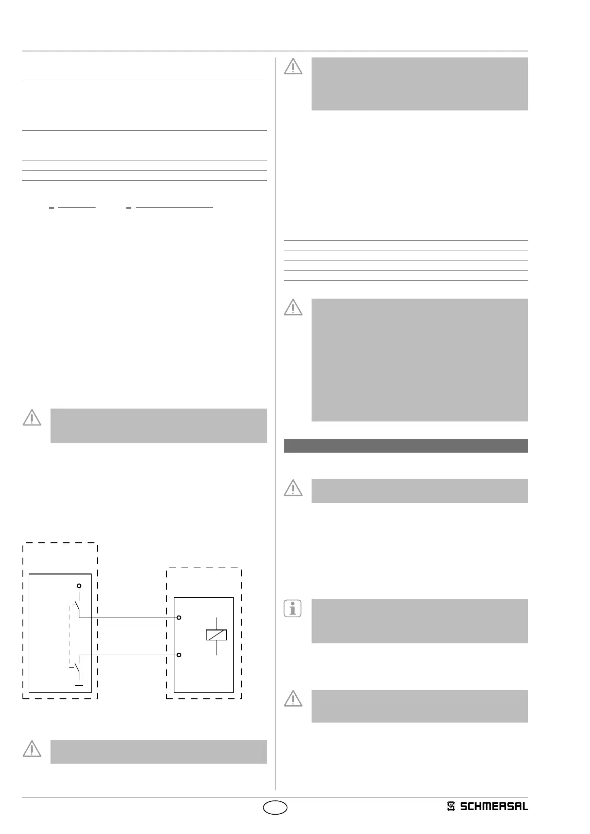
The following safety classification of the unlocking function is based
on the application of the principle of safety energy disconnection for the
solenoid supply.
The classification of the unlocking function is only valid for
devices with monitored guard locking function and in the
power to unlock version (see ordering code).
A fault exclusion for the guard locking function can be assumed by an
external safety energy disconnection.
In this case, the guard locking function does not have an effect on the
failure probability of the unlock function.
The safety level of the unlock function is determined exclusively by the
external safety power shutdown.
A1
A2
+24 VDC
PL ?
PFH
D
?
0 VDC
Safety power
shutdown
Safety interlock
Guard locking
function
In the safety classification of the unlock function, a fault exclusion can
be applied for the interlock.
Fault exclusion with regard to wiring routing must be
observed.
If for a certain application the power to unlock version of a
solenoid interlock cannot be used, for this exception an
interlock with power to lock can be used if additional safety
measure need to be realised that have an equivalent safety
level.
Safety classification of the interlock function on connection to the
safety fieldbox SFB
The safety field box SFB activates the unlocking function of the guard
lock with a secure and monitored output.
In the event of a fault resulting in the unlocking of the guard locking
function, it will be reliably detected by the SFB.
To simplify the safety classification of the guard locking function, the
following parameters can be assumed for connection of the solenoid
interlock to the SFB.:
Standards: EN ISO 13849-1
PL: d
Control Category: 2
PFH: ≤ 3.01 x 10
-7
/ h
Mission time: 20 years
The safety classification of the guard locking function refers
to the component solenoid interlock as part of the complete
system. In the event of a fault resulting in the unlocking of the
guard locking function, it will be reliably detected by the SFB.
If a fault is detected, the SFB passivates the slot used and
switches the safety function of the solenoid interlock in the
safety controller off. When such a fault occurs, the protective
equipment may open immediately, just once, before the safe
condition of the machine is reached. The system reaction of
category 2 allows that a fault can occur between tests
causing the loss of the safety function which is detected by
the test.
3. Assembly
3.1 General mounting instructions
Please observe the remarks of the standards EN ISO 12100,
EN ISO 14119 and EN ISO 14120.
4 M5 holes are provided for mounting the enclosure. Screws with
strength class 8.8 and a tightening torque of 1.3 to 1.5 Nm with plain
washers (not included in delivery) must be used for mounting. The
solenoid interlock is double insulated. The use of an earth wire is not
authorised. The solenoid interlock must not be used as an end stop.
Any mounting position. The mounting position must be chosen so as to
avoid the penetration of dirt in the used holes. Unused actuator
openings must be sealed with slot sealing plugs.
Detailed information on actuators with standard coding
(not included in delivery) AZM150-B1, AZM150-B5 and
AZM150-B6 and their mounting can be found in the actuator
operating instructions.
The insertion funnel on the head of the interlock allows insertion
of a flexible actuator with an axial offset of ≤ ±1 and a height offset
of ≤ ±1.
The solenoid interlock and actuator must be mounted
such that on unlocking, no tensile forces are exerted in
the direction of actuation.
 Loading...