Instructions for Use – SCHMIDT
®
Flow Sensor SS 20.600 Page 26
Analog outputs
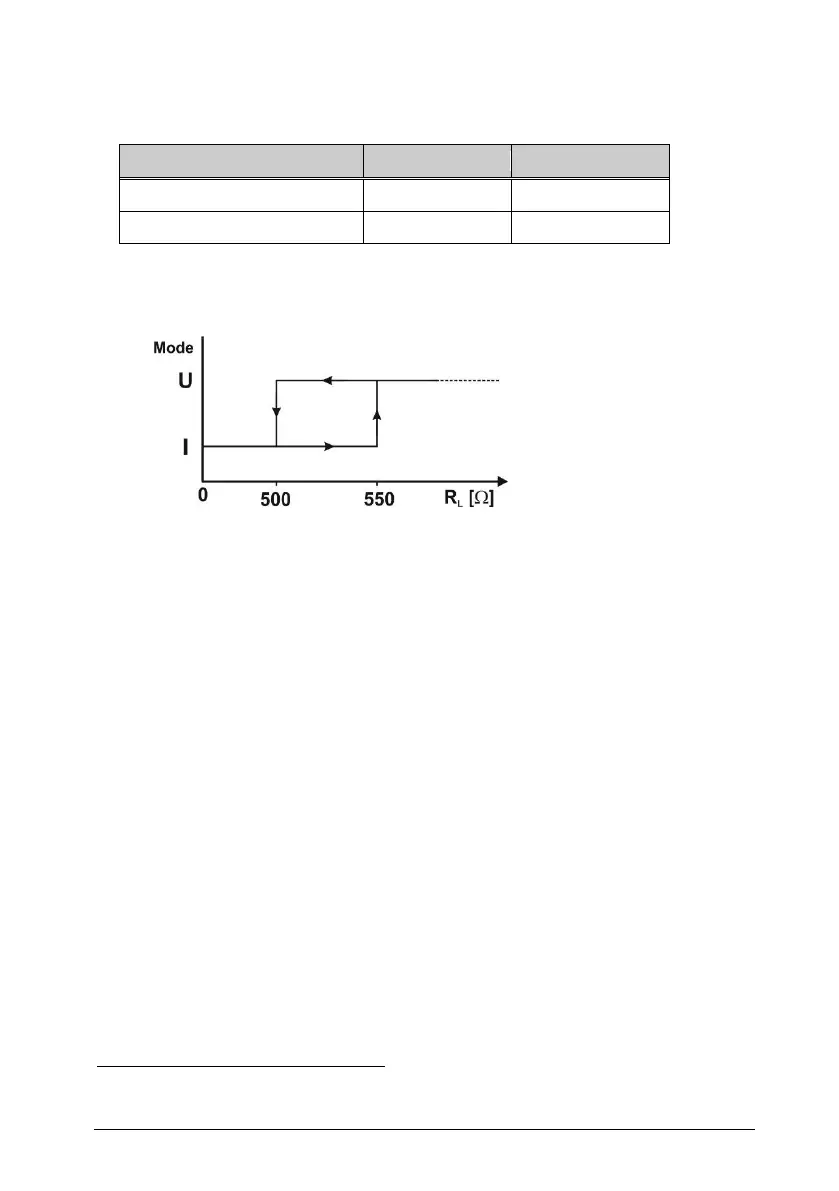
Switching characteristic Auto-U/I
Table 6
A switching hysteresis of approx. 50 Ω ensures a stable transition be-
havior (see Figure 5-2).
Figure 5-2
Depending on the provided output signal characteristic the accuracy of
the switching point detection can be reduced. Therefore, it is recom-
mended to select the load resistance such that a safe detection can be
maintained (≤ 300 Ω for current mode and ≥ 10 kΩ for voltage mode).
To detect possible alternating load in an actual zero signal, the elec-
tronics generates test pulses that correspond to an effective value of
approx. 1 mV. However, the latest measuring devices may trigger in
response to such a pulse in DC voltage measuring mode and display
short-term measuring values of up to 20 mV. In this case, it is recom-
mended to install an RC filter at the measuring input with a time con-
stant of 20 … 100 ms.
Error signaling
In current mode, the interface outputs 2 mA