16
5
Installation and Adjustment Guidelines
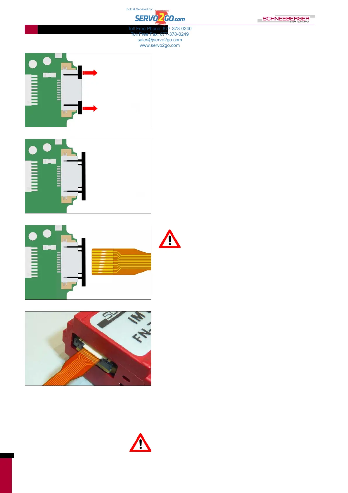
Open ZIF connector (H)
Insert the flexible printed circuit board (C) into the ZIF connector (H)
of the interface module (F) without touching the gold contact points
on the printed circuit board.
Make sure that the contact surfaces of the flexible
printed circuit board are facing upwards so that
contact is ensured.
Once the flexible printed circuit board has been inserted, push the
ZIF connector towards it.
Once the sensor is connected to the interface module, which is
connected to the grounded machine, it is protected from ESD and
can be touched without ESD protection.
The flexible printed circuit board between the sensor and the
interface module can only be used statically. The bending radius of
the flexible printed circuit board must not fall below 2 mm.
Toll Free Phone: 877-378-0240
Toll Free Fax: 877-378-0249
sales@servo2go.com
www.servo2go.com
Sold & Serviced By: