SCHOTTEL
SRP 15 .... SRP 300
No.
BA 103 E
Dat.
1-12-77
TD-NM-in
Seitenz.
19
Seite
16
- Install the SRP with well foundation (5) completely with
rubber gasket (10) in well (11).
- Connect the electric oil warning system to the flow switch
(Figure 1/6) by means of a 2 x 1.5 mm2 cable.
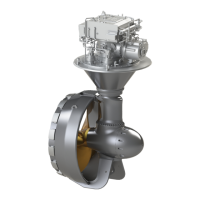
4.3 PROPELLER INSTALLATION
The installation of a flanged-on propeller in the form of a
pulling configuration does not cause any problems, so that it
is not described herein in more detail. The torque load for
the mounting screws (M 16) is 177 Nm (18.1 mkp).
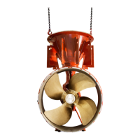
When installing a propeller on a tapered shaft (see Figures 8
and 9), pay attention to the following points:
- Remove the fitting key (Figure 8/5 or 9/1) and check that
it can be pushed through the slot of the hub bore, remachine
the slot, if required.
- Install the fitting key again, paying attention to secure
seating by the clamping sleeve.
- When installing a new propeller (spare propeller), apply
dye check paint onto the taper of the propeller shaft,
provisionally fit the propeller and check the wear pattern;
the supporting surface must be at least 70$, remachine the
propeller hub, if required.
- The labyrinth space between propeller hub and gear-box must
be free from foreign matter.
- The seating faces of the propeller shaft and hub bore must
be cleaned; the hub seat must be fitted in a hand dry
condition.
- After the propeller has been fitted (Figure 8/1 or 9/7) screw
on the propeller nut (Figures 8/3 or 9/5) and tighten the nut
by means of a wrench hammer (normally, the wrench hammer
forms part of the scope of delivery of the SCHOTTEL rudder
propeller). When the arrangement is according to Figure 8,
pay attention to the tab washer (Figure 8/2).
Caution:
When tightening the propeller nut by means of the wrench
hammer, the propulsion system must be disengaged, in order
to prevent gear teeth and bearings from being damaged.
 Loading...