OPERATION
FX-318 - FX212 08/21 Operation Section 4-14
© 2021 Alamo Group Inc.
OPERATION
NOTE: If tractor has a 540 RPM PTO, adjusting to a 16-inch position will gain additional 2 inches of
telescoping length.
Engagement Check Procedure
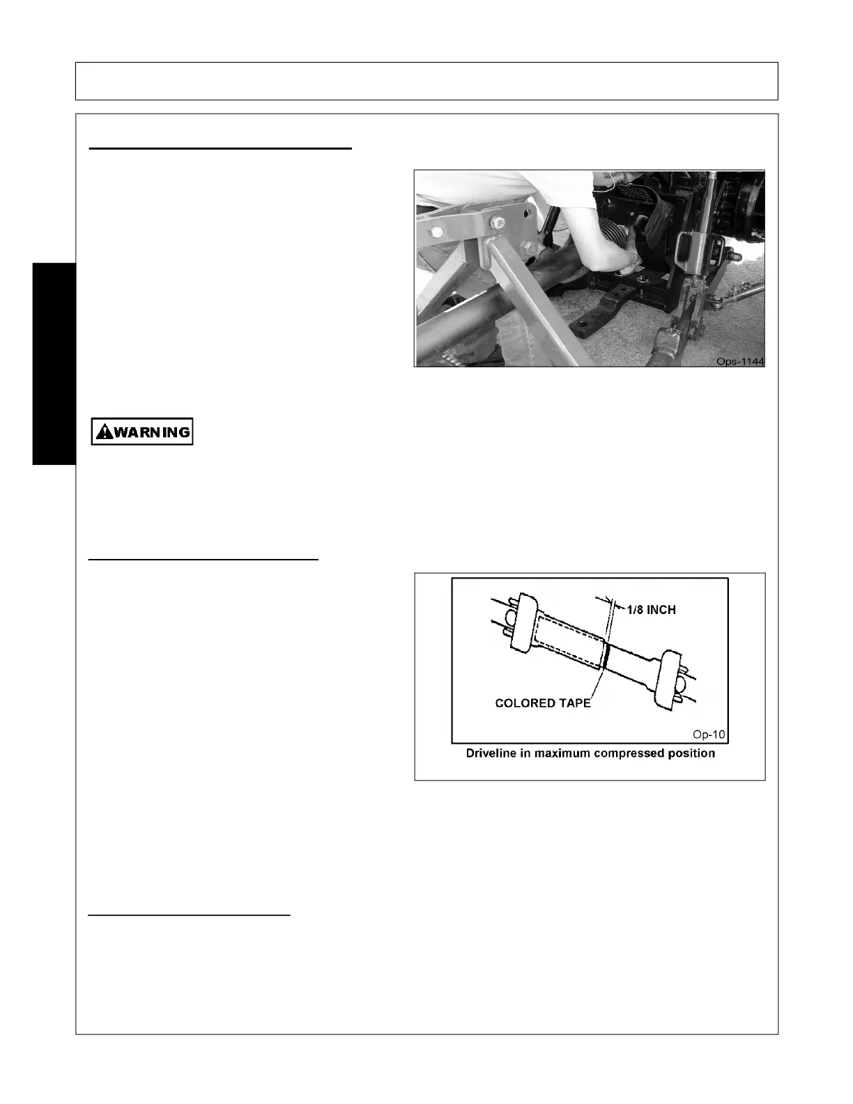
• With the driveline attached, position the mower to the point where the telescoping driveline is at its
maximum extension. Completely shut down the tractor and secure in position.
• Mark the inner driveline shield 1/8” from the end of the outer shield.
• Disconnect the driveline from the tractor and separate the two driveline halves.
7. DRIVELINE ATTACHMENT
The driveline yoke and tractor PTO shaft must be
dirt free and greased for attachment.
To connect the mower driveline to the tractor PTO
output shaft, twist the driveline yoke collar and align
the grooves and splines of the yoke with those of
the PTO shaft. Push the driveline yoke onto the
PTO shaft, release the locking collar, and position
the yoke until the locking collar balls are seated
onto the PTO shaft. Push and pull the driveline
back and forth several times to ensure a secure
attachment. OPS-R-0003_G
When attaching the Implement input driveline to the Tractor PTO, it is important that the
connecting yoke spring activated locking collar slides freely and the locking balls are seated
securely in the groove on the Tractor PTO shaft. Push and pull the driveline back and forth
several times to ensure it is securely attached. A driveline not attached correctly to the
Tractor PTO shaft could come loose and result in personal injury and damage to the
Implement.
(S3PT-17)
“Bottoming Out” Check Procedure
• Disconnect driveline from the tractor and slide
the profiles together until fully compressed.
• Place a mark on the inner shield 1/8” from the
end of the outer shield and reattach the
driveline to the PTO shaft.
• With the PTO NOT TURNING, slowly drive the
tractor with mower attached through the
sharpest turn possible and watch shaft
movement. With the PTO NOT TURNING,
slowly drive the tractor with the mower attached
through the most severe terrain conditions
expected and watch shaft movement.
• If the distance between the mark and the outer
shield becomes less than 2” at any point there is a potential problem bottoming out the driveline and the
driveline should be replaced with shorter driveline. Contact your local dealer or Technical Service for
proper directions. OPS-R-0004_J