Assembly and settings
10 01.00 | MMS 22-IOL | Assembly and Operating Manual | en | 1598377
l
Check whether there is sufficient distance between the sensor
and sources of interference and their supply cables.
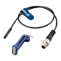
Connection diagram (SIO operation)
Connection diagram (IO-Link operation)
OUT
Type of switching PNP
Switching function Closer
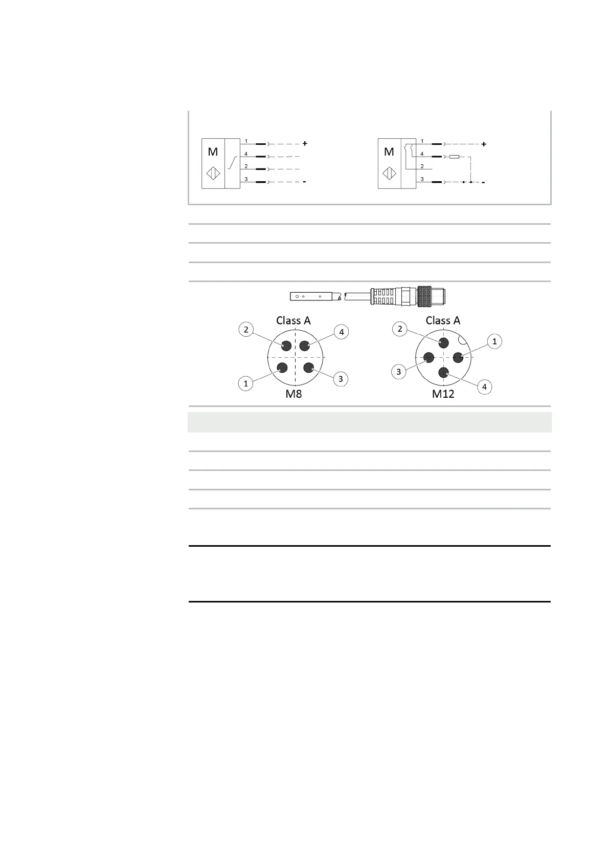
Cable length [m] 0.3
Connector M8 / M12
Pin Signal Description
1 L+ +24 V
2 I/Q not assigned
3 L- GND
4 C/Q Switching signal DI (SIO) or IO-Link (SDCI)
5.3 Adjusting the sensor
NOTE
The difference between the teach and operating temperatures
must not exceed 30 K.
5.3.1 IO-Link mode
In IO-Link mode, the sensor is used to record positions on
SCHUNK products. To do so, the exact limits must be taught in.
This can be done with a teach-in tool (sensor in SIO mode) or by
the software (sensor in IO-Link mode via IO-Link master).