SEL-487V Data Sheet Schweitzer Engineering Laboratories, Inc.
10
Close-up views of the front panel of the SEL-487V are
shown in Figure 8, Figure 9, and Figure 10. The front
panel includes a 128 pixel by 128 pixel, 3 in. by 3 in.
LCD screen, LED target indicators, and pushbuttons with
indicating LEDs for local control functions. The asserted
and deasserted colors for the LEDs are programmable.
Configure any of the direct-acting pushbuttons to
navigate directly to an HMI menu item, such as events,
bay display, alarm points, display points, or the SER.
Status and Trip Target LEDs
The SEL-487V includes programmable status and trip
target LEDs, as well as programmable direct-action
control pushbuttons/LEDs on the front panel. These
targets are shown in Figure 8 and Figure 10 and are
explained in Table 4.
The SEL-487V features a versatile front panel that you
can customize to fit your needs. SEL
OGIC control
equations and slide-in configurable front-panel labels
change the function and identification of target LEDs
and operator control pushbuttons and LEDs. The blank
slide-in label set is included with the SEL-487V. Label
sets can be printed from a laser printer using templates
supplied with the relay or hand labeled on supplied blank
labels.
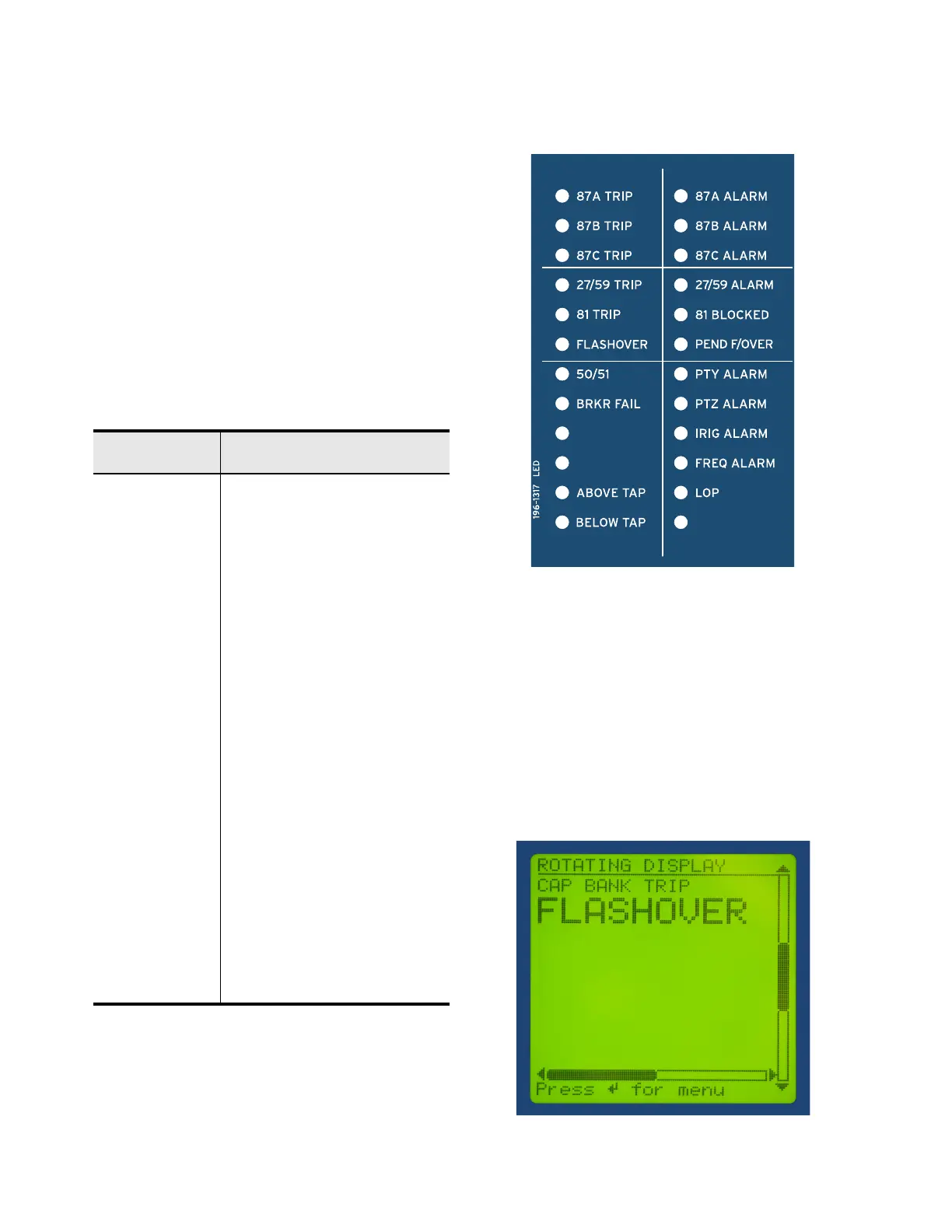
Figure 10 Programmable Status and Trip Target LEDs
Advanced Display Points
Create custom screens showing metering values, special
text messages, or a mix of analog and status information.
Figure 11 shows an example of how display points can
be used to show circuit breaker information and current
metering. As many as 96 display points can be created.
All display points occupy only one line on the display at
all times. The height of the line is programmable as
either single or double (see Figure 11). These screens
become part of the autoscrolling display when the front
panel times out.
Figure 11 Sample Display Points Screen
Table 4 Description of Factory-Default Target LEDs
ENABLED
Relay Powered Properly and
Self-Tests Okay
TRIP Indication that a trip occurred
87A TRIP A-Phase Voltage Differential Asserted
87B TRIP B-Phase Voltage Differential Asserted
87C TRIP C-Phase Voltage Differential Asserted
27/59 TRIP Under/Overvoltage Trip
81 TRIP Under/Overfrequency Trip
FLASHOVER Breaker Flashover Detected
50/51 Overcurrent Element Asserted
BRKR FAIL Breaker Failure Element Asserted
ABOVE TAP Differential Fault Above Tap
BELOW TAP Differential Fault Below Tap
87A ALARM A-Phase Differential Alarm
87B ALARM B-Phase Differential Alarm
87C ALARM C-Phase Differential Alarm
27/59 ALARM Under/Overvoltage Alarm
81 BLOCKED Frequency Element Blocked
PEND F/OVER Breaker Flashover Pending
PTY ALARM Potential Transformer Y Alarm
PTZ ALARM Potential Transformer Z Alarm
IRIG ALARM IRIG Clock Alarm
FREQ ALARM Frequency Tracking Alarm
LOP Loss-of-Potential Condition