A-CR-CCP-402/MB-001 SCHWEIZER 2-33 AOIs
2-2
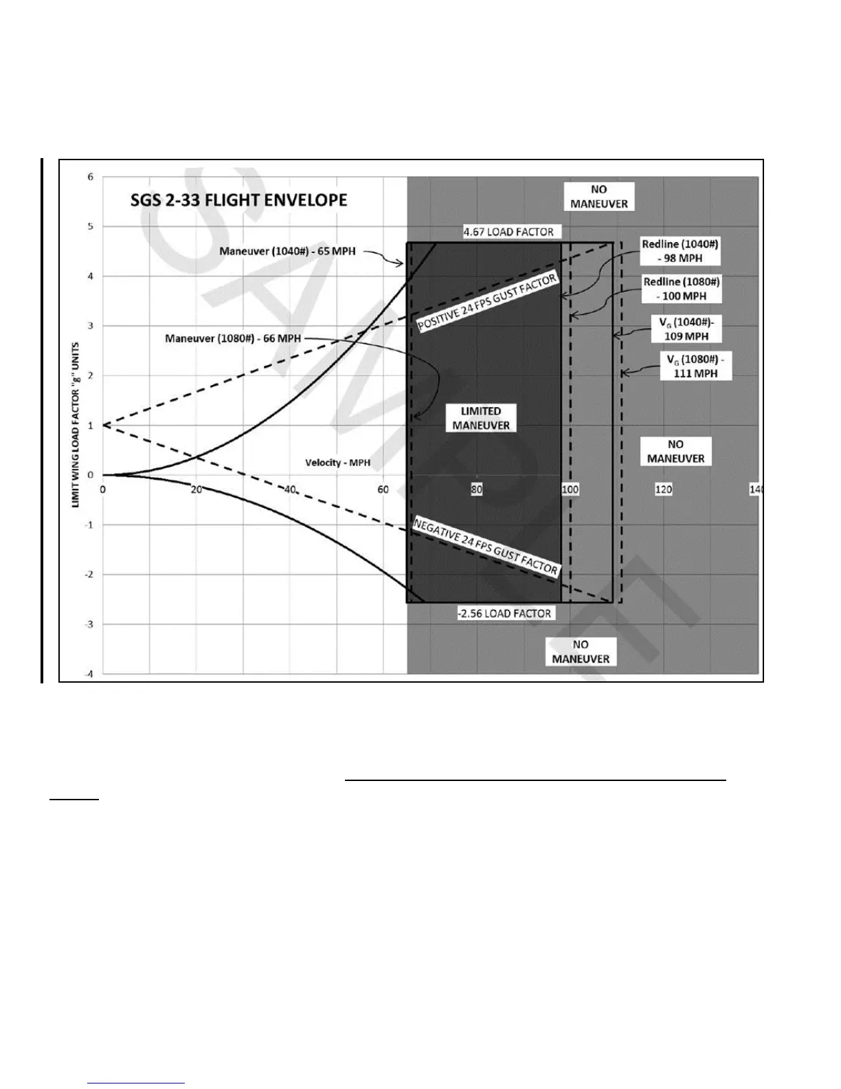
Figure 2-3 The Flight Envelope (added 2016)
UNDERSTANDING THE FLIGHT ENVELOPE
The following paragraphs are taken from The SGS 2-33 Sailplane Flight-Erection-Maintenance
Manual, K&L Soaring and are provided to assist with understanding Figure 2-3 Flight Envelope:
"The FAA* required design flight envelope is presented on the
[graph]. On the horizontal axis are indicated velocities in miles per
hour, and on the vertical axis are load factors expressed in "G" units.
The straight lines labeled [sic] "gust load factors" represent the effect
of the FAA required 24 ft. per second gust on the sailplane as speed
varies. They diverge from the one "G" situation where the glider
would be at rest or in perfectly balanced level flight. The curved lines
diverging from zero "G" represent forces which can be induced by
moving the elevator (or other) control abruptly at various speeds. As
you can see, the faster you fly the more effect moving your controls