99
Maintenance
SP 500 / 750-15 / 750-18 / 1000 / 1250 Operation Manual
Inspect Bolts on Rams
Each day, visually inspect the bolts on the rubber rams.
If you see something unusual, shut o the engine, put
the key in your pocket and remove the waterbox cov-
ers and inspect with a wrench. If you nd that they are
loose, tighten with a torque wrench to the “Torque Spec-
ications for Metric Bolts” listed in the Appendix section.
Remember to replace the waterbox covers before using
the machine.
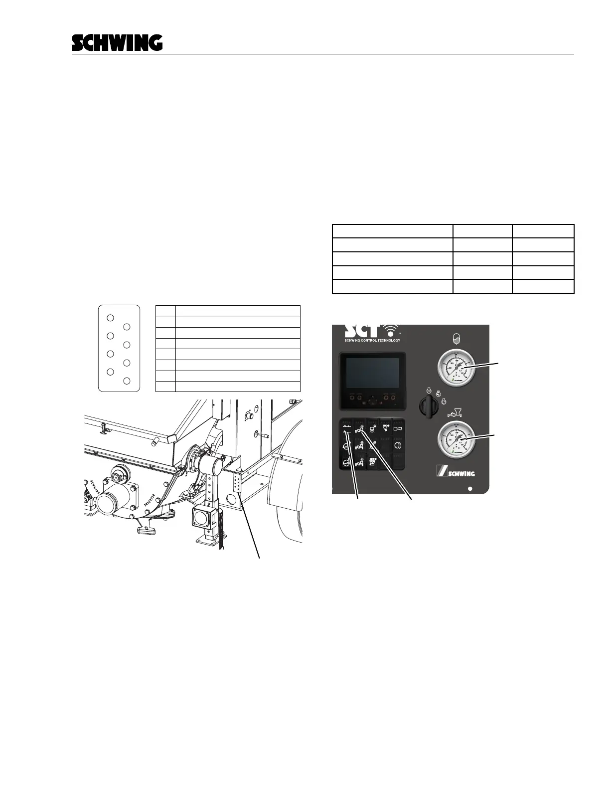
Grease the Rock Valve and Agitator Bearings
Grease the Rock Valve and agitator bearings using the
manual greasing station located on the rear, passenger
side of the stationary pump (Figure 6). If your unit was
equipped with the optional automatic greasing system,
check the grease levels each day and check for any
damage or leaks in the system.
Manual Greaser Station
Right Hand Inside Shift Cylinder
Left Hand Shift Cylinder
Right Hand Shift Cylinder
Right Hand Agitator
Left Hand Inside Shift Cylinder
Left Hand Side Agitator
Front Rock Pivot
Rear Rock Pivot
1
2
3
4
5
6
7
8
5
6
7
8
1
2
3
4
Figure 6
Agitator Grease Points
Inspect for Damage or Leaks
Visually inspect the unit for damage or leaks each day.
Repairs should be made before the unit is operated.
Check if Maintenance is due
Check your “Scheduled Maintenance Checklist” to see
if any weekly, monthly, semiannual, or annual mainte-
nance is due.
Check hydraulic pressures
Check your main pressure cut-o, soft switch and ac-
cumulator pressure cut-o settings. Pressure relief set-
tings are shown below and on the hydraulic schematic
that shipped with this unit. Changes in pressures may
indicate trouble in one or more hydraulic components.
Pressure Cut-O 300 bar
Main Relief 320 bar
Soft Switch 100 bar
Accumulator Pressure Cut-O 200 bar
ACC2ACC1
ACC3
ACC
98413629-00
Concrete Pump
Pressure Gauge
Button
Concrete Pump
Forward Button
Accumulator
Pressure Gauge
Figure 7
Rear operator panel and pressure gauges.