1981-93 Dodge Pickup, Ramcharger
Read pages 2-4
1981-93 Plymouth Trailduster
for kit assembly.
RADIO REMOVAL:
1. Remove five screws from the edge of the dash panel.
2. Remove one screw from the dash panel above the radio.
3. Carefully pull out the bottom of the panel to release the panel clips and remove the panel.
4. Remove two screws securing the radio to dash and pull out the radio.
5. Disconnect the power, antenna, and all speaker and electrical connections.
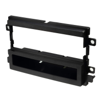
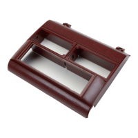
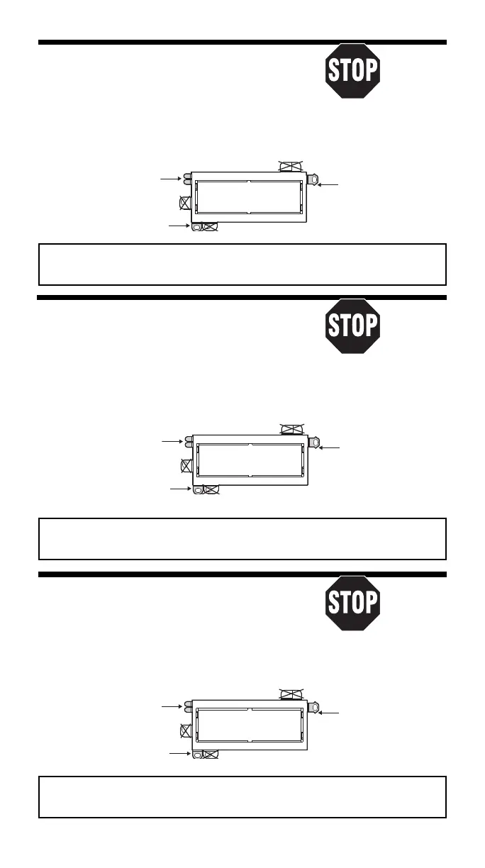
USE THESE SUPPORT
#2190 PANEL
REMOVE ALIGNMENT
TABS AS REQUIRED
PIN - BOTTOM
Usar tantas de estas
Sacar la clavija de
pestañas como sea
alineamiento - Inferior
necesario
USE THIS BRACKET
Usar este braquete
USE THE SHADED MOUNTING TABS AND THE INDICATED BRACKETS. CUT OFF THE REMAINING TABS
AND DISCARD. FOR DIN ISO INSTALLATION, SEE PAGE 4.
Usar las pestañas sombreadas y los braquetes indicados. Cortar las pestañas restantes y descartarlas.
Para la instalación de radios DIN ISO ver la página 4.
1974-80 Dodge Pickup, Ramcharger
Read pages 2-4
1974-80 Plymouth Trailduster
for kit assembly.
RADIO REMOVAL:
1. Remove four screws from the top edge of the dash panel.
2. Remove seven screws on the front surface and three under the dash panel.
3. Carefully pull the panel from the dash and remove it.
4. Remove two screws securing the radio to the dash. Pull the radio out.
5. Disconnect the power, antenna, and all speaker and electrical connections.
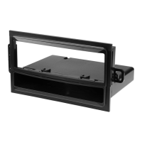
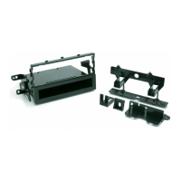
#2190 PANEL
USE THESE SUPPORT
TABS AS REQUIRED
Usar tantas de estas
pestañas como sea
necesario
USE THIS BRACKET
Usar este braquete
REMOVE ALIGNMENT
PIN - BOTTOM
Sacar la clavija de
alineamiento - Inferior
USE THE SHADED MOUNTING TABS AND THE INDICATED BRACKETS. CUT OFF THE REMAINING TABS
AND DISCARD. FOR DIN ISO INSTALLATION, SEE PAGE 4.
Usar las pestañas sombreadas y los braquetes indicados. Cortar las pestañas restantes y descartarlas.
Para la instalación de radios DIN ISO ver la página 4.
1998-01 Dodge Ram
Read pages 2-4
RADIO REMOVAL:
for kit assembly.
1. Extract one Screw from lighter socket area.
2. Carefully pry out on the radio dash bezel to release the fastening
clips, disconnect all connectors and remove the bezel.
3. Extract the two screws securing the radio to the dash, pull the radio from the dash cavity,
unplug all connectors, diconnect the ground strap and remove the radio.
USE THESE SUPPORT
TABS AS REQUIRED
#2190 PANEL
REMOVE ALIGNMENT
PIN - BOTTOM
Usar tantas de estas
Sacar la clavija de
necesario
pestañas como sea
alineamiento - Inferior
USE THIS BRACKET
Usar este braquete
USE THE SHADED MOUNTING TABS AND THE INDICATED BRACKETS. CUT OFF THE REMAINING TABS
AND DISCARD. FOR DIN ISO INSTALLATION, SEE PAGE 4.
Usar las pestañas sombreadas y los braquetes indicados. Cortar las pestañas restantes y descartarlas.
Para la instalación de radios DIN ISO ver la página 4.
15
 Loading...