EasyManua.ls Logo

Scotsman CU1526 Service Manual

Scotsman CU1526
62 pages
To Next Page IconTo Next Page
Page #1 background imageLoading...
Page #1 background image
Introduction
The design of this cuber is the result of years of
experience and testing. Standard features include
a removable bin for service and an on-off switch at
the front of the cabinet for easy operational control.
Note any Caution or Warning symbols when they
appear on the product or in this manual. They
indicate potential hazards.
May 2008
Page 1
CU1526, CU2026, CU3030
Service Manual
Table of Contents
Installation: Product Specifications ..... Page 2
Model Number Description.......... Page 3
Water .....................Page 4
CU1526 and CU2026 Cabinet Layout .... Page 5
CU3030 Cabinet Layout ........... Page 6
Bin Removal ................. Page 7
Plumbing Requirements ........... Page 8
Electrical ................... Page 9
Adjustments ................. Page 10
Use and Operation .............. Page 11
Control Switches ............... Page 12
Cuber System Information .......... Page 13
Controller Information ............ Page 14
Component Indicator Light Table ...... Page 15
How It Works - Air Cooled .......... Page 16
How It Works - Water Cooled ........ Page 17
Electrical Sequence - Air or Water Cooled . Page 18
Electrical Component Details ........ Page 20
Electrical Component Details - continued . . Page 21
Refrigeration & Water Systems ....... Page 22
Control Operation .............. Page 23
Control Safeties ............... Page 24
Restarts ................... Page 25
Control Button Use .............. Page 26
Test Mode: .................. Page 27
Service Diagnosis .............. Page 28
Service Diagnosis .............. Page 29
Service Diagnosis .............. Page 30
Service Diagnosis - Low ice making capacity - air cooled
........................Page 31
Cleaning, Sanitation and Maintenance . . . Page 32
Test Procedures - Sensors ......... Page 34
Sensor Testing ................ Page 35
Thermistors ................. Page 36
Test Procedures - Loads ........... Page 37
Test Procedures ............... Page 38
Technical Information ............ Page 41
Performance Data, CU1526
......... Page 42
Performance Data, CU2026 ......... Page 43
Performance Data, CU3030 ......... Page 44
Wiring Diagram, CU1526 and CU2026 60 Hz up to
Serial Number 12021320013437 ...... Page 45
Wiring Diagram, CU1526 and CU2026 60 Hz after Serial
Number 12021320013437 .......... Page 46
Wiring Diagram, CU3030 60 Hz up to Serial Number
TBD ..................... Page 47
Wiring Diagram, CU3030 60 Hz after Serial Number
TBD ..................... Page 48
Wiring Diagram, CU1526 and CU2026 50 Hz up to
Serial Number 12021320013437 ...... Page 49
Wiring Diagram, CU1526 and CU2026 50 Hz after Serial
Number 12021320013437 .......... Page 50
Wiring Diagram, CU3030 50 Hz up to Serial Number tbd
Page 51
Wiring Diagram, CU3030 50 Hz after Serial Number tbd
Page 52
Removal and Replacement ......... Page 53
Refrigeration Removal and Replacement Procedures
........................Page 59
Refrigeration Removal and Replacement Procedures
........................Page 62

Table of Contents

Other manuals for Scotsman CU1526

Question and Answer IconNeed help?

Do you have a question about the Scotsman CU1526 and is the answer not in the manual?

Scotsman CU1526 Specifications

General IconGeneral
Ice TypeCube
Condenser TypeAir-cooled
TypeUndercounter
RefrigerantR-404A
Voltage115V

Summary

Introduction to the Ice Cuber

Product Installation and Specifications

Location and Space Limitations

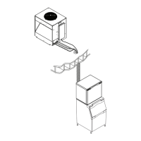
Details requirements for unit placement, airflow, and service access.

Environmental Operating Limitations

Specifies acceptable ambient and water temperature and pressure ranges.

Electrical Power Supply Requirements

Outlines acceptable voltage ranges for the unit's power supply.

Warranty and Product Overview

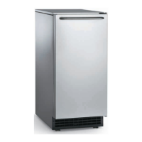
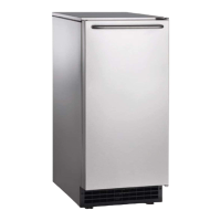
Information on warranty coverage and general product description.

Model Number Identification

Water System Considerations

Water Quality and Purge Function

Discusses water quality impact, RO water, and the water purge system.

Airborne Contamination Prevention

Addresses potential contamination from airborne sources and mitigation.

Cabinet Layout Diagrams

CU1526 and CU2026 Cabinet Dimensions

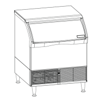
Provides detailed dimensional drawings for CU1526 and CU2026 models.

CU3030 Cabinet Dimensions

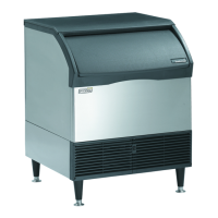
Provides detailed dimensional drawings for the CU3030 model.

Bin Removal Procedure

Plumbing and Water Connections

Water Inlet and Drain Requirements

Details water supply connections and drain tubing requirements.

Drain Tubing Installation Guidelines

Provides instructions for routing and installing drain tubing.

Electrical Connections and Cycle Times

Electrical Safety and Grounding

Emphasizes electrical safety, grounding, and avoiding extension cords.

Typical Ice Making Cycle Times

Lists expected cycle times under various temperature conditions.

Adjustments for Ice Thickness and Water Purge

Adjusting Ice Bridge Thickness

Procedure for service technicians to adjust ice thickness.

Setting the Water Purge Level

Instructions for setting water purge from automatic to manual options.

Understanding Unit Operation and Indicators

Automatic Ice Making Cycle

Describes how the ice machine operates automatically.

Indicator Lights and Their Meanings

Explains the function of each indicator light on the control box.

Control Switches and Operation Modes

Front and Controller Switch Functions

Details the operation of front and internal controller switches.

Controller Indicator Light Codes

Lists codes and descriptions for controller indicator lights.

System Components and Configuration

Overview of System Types

Describes refrigeration, water, control, and harvest systems.

List of Electrical Components

Enumerates the electrical components within the ice machine.

Controller Functions and Codes

Controller Main and Setting Codes

Details the codes displayed by the controller for cycles and diagnostics.

Component Indicator Light Mapping

Indicator Light Status for Components

Table mapping component operation to indicator light status.

Ice Making Process - Air Cooled Models

Air Cooled Freeze Cycle Explanation

Describes the freeze cycle for air-cooled ice machines.

Air Cooled Harvest Cycle Explanation

Describes the harvest cycle for air-cooled ice machines.

Ice Making Process - Water Cooled Models

Water Cooled Freeze Cycle Explanation

Describes the freeze cycle for water-cooled ice machines.

Water Cooled Harvest Cycle Explanation

Describes the harvest cycle for water-cooled ice machines.

Electrical Sequence of Operation

Ice Making Sequence and Light Status

Details the electrical sequence for ice making and indicator light status.

Harvest Cycle Electrical Sequence

Harvest Sequence and Indicator Information

Describes the harvest cycle sequence and related indicator information.

Details of Electrical Components

Compressor and Contactor Details

Explains the operation of the compressor and contactor.

Water Pump, Purge Valve, and Fan Motor

Details the function of the water pump, purge valve, and fan motor.

High Pressure Cut Out and Harvest Solenoid

Describes the high pressure cut out and harvest assist solenoid.

Continued Electrical Component Descriptions

Hot Gas Valve, Controller, and Transformer

Details the hot gas valve, controller, and transformer.

Sensors and Curtain Switch Functions

Explains the water sensor, ice thickness sensor, and curtain switch.

Temperature Sensor Details

Describes the water and discharge temperature sensors.

Refrigeration and Water System Overview

Refrigeration System Components

Details refrigerant, compressor, expansion valve, and condenser.

Water System Components

Describes water reservoir, valve, pump, sensor, and distributor.

Control System Operation

Standard Control Unit and Indicator Lights

Explains the electronic controller and its indicator lights.

Controller Terminal Connections

Lists and describes the controller connection terminals.

Control System Safety Limits

Maximum and Minimum Freeze Time Safeties

Details safety limits for freeze cycle duration.

Maximum Harvest Time and Reset Parameters

Specifies harvest time limits and reset conditions.

Automatic Restarts and Interruption Handling

Restarts After Power Interruption

Describes how the unit restarts after a power loss.

Restarts After Water Interruption

Explains how the unit handles and restarts after water supply issues.

Control Button Functions and Modes

Setting Purge Levels

Instructions for setting water purge levels via control buttons.

Diagnostic Code Recall and Clearing

Procedures for recalling and clearing diagnostic error codes.

Control Reset and Test Mode Activation

Steps for resetting the control and entering test mode.

Control Lock/Unlock and Reservoir Emptying

Instructions for locking controls and manually emptying the reservoir.

Diagnostic Test Modes and Settings

Test Mode Sequence for Air/Water Cooled

Details the sequence of operations during test mode.

Adjusting De-Scale Notification Interval

Procedure to change the interval for de-scale reminders.

Troubleshooting: No Ice and Fill Time Issues

Diagnosing 'No Ice' Problems

Likely causes and solutions for a lack of ice production.

Troubleshooting Maximum Water Fill Time

Identifies issues causing shutdown during maximum water fill time.

Troubleshooting Maximum Freeze Time Shutdowns

Addresses causes for shutdown during maximum freeze time.

Troubleshooting Freeze Time and Compressor Issues

Further Troubleshooting for Freeze Time Shutdowns

Continues diagnosis for maximum freeze time issues.

Diagnosing Compressor Not Operating

Identifies causes and solutions when the compressor fails to run.

Troubleshooting Harvest and Freeze Time Issues

Diagnosing Maximum Harvest Time Shutdowns

Identifies causes and solutions for shutdown during maximum harvest time.

Diagnosing Minimum Freeze Time Issues

Addresses causes for shutdown during minimum freeze time.

Troubleshooting Low Ice Capacity and Noise

Low Ice Making Capacity Diagnosis

Troubleshooting steps for reduced ice production capacity.

Diagnosing Excessive Noise in Air Cooled Models

Identifies causes and solutions for unusual noise.

Routine Cleaning and Maintenance Procedures

Ice Machine Cleaning and Sanitation Steps

Detailed procedure for cleaning and sanitizing the ice machine's water system.

Component Cleaning and Filter Maintenance

Cleaning Air Cooled Condenser Filter

Instructions for cleaning the air cooled condenser filter.

Cleaning Air Cooled Condenser Fins

Guidance on cleaning the air cooled condenser fins.

Exterior Panel Cleaning

Recommendations for cleaning the unit's exterior panels.

Water Filter Cartridge Maintenance

Information on checking and replacing water filter cartridges.

Sensor Testing Procedures

Curtain Switch Testing

Methods for testing the curtain switch functionality.

Ice Thickness Sensor Testing

Procedures for testing the ice thickness sensor.

Additional Sensor Diagnostics

Water Sensor Testing and Function

Tests to verify water sensor operation and conductivity sensing.

Temperature Sensor Testing

Procedures for testing water and discharge temperature sensors.

Thermistors Resistance Chart

Testing Major Electrical Loads

Compressor Testing Procedures

Diagnostic steps for compressor failure to start and amp draw.

Fan Motor Testing Procedures

Methods for testing fan motor operation and voltage supply.

Testing Water Pump and Purge Valve

Water Pump Testing and Resistance Check

Procedures for testing water pump indicator light and resistance.

Purge Valve Testing and Voltage Check

Methods for testing purge valve operation and voltage.

Testing Contactor, Pressure Switches, and Transformer

Compressor Contactor Testing

Diagnostic steps for the compressor contactor.

Pressure Switch Testing Procedures

Tests for fan and high pressure cut out switches.

Transformer Secondary Voltage Check

Verifies the transformer's output voltage.

Testing Controller, Hot Gas Valve, and Solenoid

Controller Functionality Test

Confirms controller software operation and load control.

Hot Gas Valve and Harvest Solenoid Testing

Procedures for testing hot gas valve and harvest assist solenoid.

Technical Specifications and Performance Data

Pressure Control Settings

Lists cut-in and cut-out pressures for fan and high pressure controls.

Compressor Amp Draw Specifications

Details compressor amp draw under different conditions.

Refrigerant Charge and Superheat Values

Specifies refrigerant charge and superheat requirements.

Performance Data CU1526

CU1526A Performance Metrics

Provides cycle time, suction, and discharge pressure data for CU1526A.

CU1526W Performance Metrics

Provides cycle time, suction, and discharge pressure data for CU1526W.

Performance Data CU2026

CU2026A Performance Metrics

Provides cycle time, suction, and discharge pressure data for CU2026A.

CU2026W Performance Metrics

Provides cycle time, suction, and discharge pressure data for CU2026W.

Performance Data CU3030

CU3030A Performance Metrics

Provides cycle time, suction, and discharge pressure data for CU3030A.

CU3030W Performance Metrics

Provides cycle time, suction, and discharge pressure data for CU3030W.

Wiring Diagram CU1526/CU2026 60Hz (Up to S/N 12021320013437)

Wiring Diagram CU1526/CU2026 60Hz (After S/N 12021320013437)

Wiring Diagram CU3030 60Hz (Up to S/N TBD)

Wiring Diagram CU3030 60Hz (After S/N TBD)

Wiring Diagram CU1526/CU2026 50Hz (Up to S/N 12021320013437)

Wiring Diagram CU1526/CU2026 50Hz (After S/N 12021320013437)

Wiring Diagram CU3030 50Hz (Up to S/N TBD)

Wiring Diagram CU3030 50Hz (After S/N TBD)

Component Removal and Replacement: Water Reservoir

CU1526/CU2026 Water Reservoir Removal

Step-by-step instructions for removing the water reservoir on CU1526/CU2026.

CU3030 Water Reservoir Removal

Step-by-step instructions for removing the water reservoir on CU3030.

Component Removal and Replacement: Float Valve

CU1526/CU2026 Float Valve Removal

Instructions for removing the float valve on CU1526/CU2026.

CU3030 Float Valve Removal

Instructions for removing the float valve on CU3030.

Component Removal and Replacement: Water Pump

CU1526/CU2026 Water Pump Removal

Instructions for removing the water pump on CU1526/CU2026.

CU3030 Water Pump Removal

Instructions for removing the water pump on CU3030.

Component Removal and Replacement: Purge Valve and Water Level Sensor

Purge Valve Removal Procedure

Step-by-step guide for removing the purge valve.

Water Level Sensor Removal Procedure

Instructions for removing the water level sensor.

Component Removal and Replacement: Fan Motor and Blade

Refrigeration Component Removal: Thermostatic Expansion Valve

Refrigeration Component Removal: Compressor

Refrigeration Component Removal: Evaporator

Final Steps for Evaporator Replacement

Related product manuals