13
and emptied of compressed air. Refer to current applicable pub-
lications on compressed gas cylinder inspection available from
Compressed Gas Association Inc., 1725 Jefferson Davis Hwy.,
Suite 1004, Arlington, VA 22202, (703-412-0900) for a detailed ex-
planation of cylinder inspection procedures.
4. Check cylinder pressure gauge for “FULL” indication. If cylin-
der pressure is less than “FULL,” replace with a fully charged
cylinder.
5. Check to ensure reducer coupling is secure to the cylinder valve
outlet.
6. Check that the breathing regulator purge valve (red knob on regu-
lator) is closed (full clockwise and pointer on knob upward).
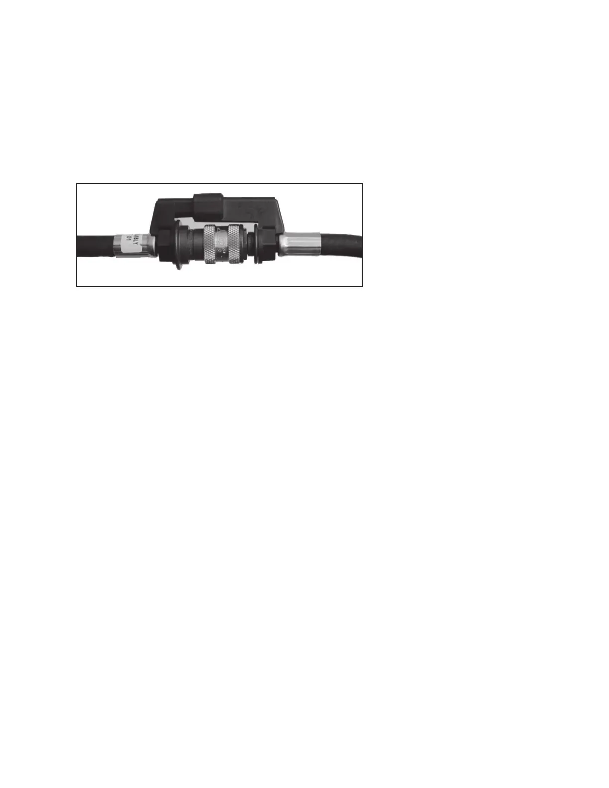
7. If the hose to the breathing regulator is equipped with a quick dis-
connect (See STANDBY INSPECTION, CLEANING AND STOR-
AGE Section for instruction on operation of the quick disconnect
coupling on regulator assemblies), check that the quick discon-
nect is engaged properly by tugging on the coupling. The Pull-back
Sleeve Quick Disconnect is shown in FIGURE 2.
8. Fully depress the center of the air saver/donning switch on the
top of the regulator and release.
9. Slowly open the cylinder valve by fully rotating knob counterclock-
wise. VIBRALERT alarm shall actuate and then stop. The HEADS-
UP DISPLAY will initialize with all five lights on for twenty seconds
followed by display of cylinder supply level. If the LOW BATTERY
light at the far right of the display remains lit or begins to flash,
replace the battery according to the BATTERY REPLACEMENT
section of this instruction before proceeding.
If the respirator is equipped with the PASS DEVICE distress alarm,
the distress alarm will be actuated when the cylinder valve is
opened. Refer to operating and maintenance instructions of the
PASS DEVICE distress alarm for the operational inspection of the
PASS DEVICE distress alarm.
10. Don the facepiece or hold the facepiece to the face to effect a
good seal. Inhale sharply to automatically start the flow of air.
Breathe normally from the facepiece to ensure proper operation.
11. Remove facepiece from face. Air shall freely flow from the face-
piece.
12. Fully depress the center of the air saver/donning switch on the
top of regulator and release. The flow of air from the facepiece
shall stop. Examine the complete respirator for air leaks. There
shall be no leakage of air from any part of the respirator.
13. Rotate purge valve 1/2 turn counterclockwise (pointer on knob
downward). Air shall freely flow from the regulator.
14. Rotate purge valve 1/2 turn clockwise to full closed position
(pointer on knob upward). Air flow from regulator shall stop.
WARNING
FAILURE TO CHECK ENGAGEMENT OF THE
COUPLING AS DESCRIBED MAY LEAD TO
HOSE SEPARATION AND LOSS OF BREATH-
ING AIR RESULTING IN SERIOUS INJURY
OR DEATH.
REGULAR OPERATIONAL INSPECTION
CONTINUED ON NEXT PAGE...
FIGURE 2
PULL-BACK SLEEVE QUICK DISCONNECT
CAUTION
DO NOT USE TOOLS TO OPEN OR CLOSE
THE PURGE VALVE. OPEN OR CLOSE BY
USING FINGER-PRESSURE ONLY. ROTA-
TION OR THE PURGE VALVE IS LIMITED TO
1/2 TURN. USE OF TOOLS TO OPEN OR
CLOSE PURGE VALVE MAY RESULT IN
DAMAGE TO THE PURGE VALVE.
 Loading...