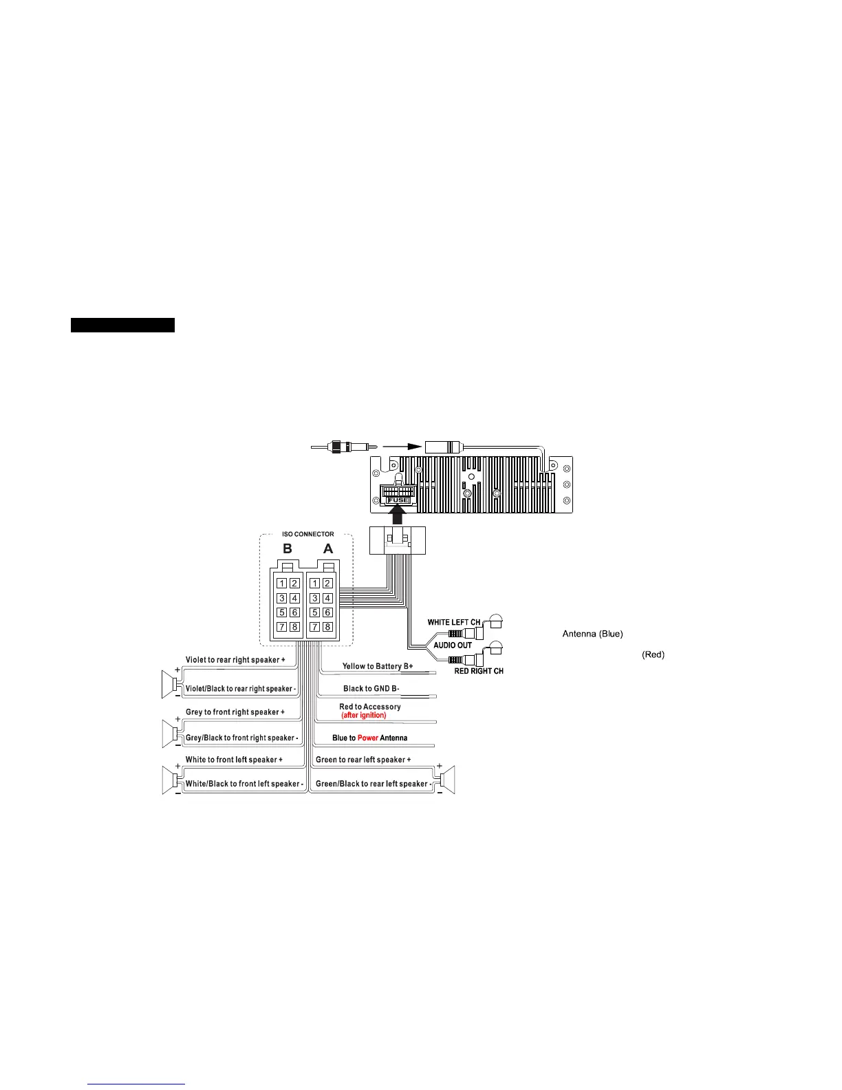
EasyManuals Logo

SCOTT I-XCR 100 User Manual

SCOTT I-XCR 100
26 pages
To Next Page IconTo Next Page
To Previous Page IconTo Previous Page
Page #9 background imageLoading...
Page #9 background image
GB-8
WIRING DIAGRAM
Many vehicles are fitted with ISO connectors behind the dashboard, which makes it easier to connect your car radio. These connections can be
found in the dashboard where the car radio will be fitted. Use these cables to connect the car radio. Should your car not be fitted with these ISO
connectors, we strongly advise you to consult your car dealer or a specialist to obtain the right adaptor. Once you have these cables, you will
need to connect your loudspeakers and the power supply to the ISO connector, following the connection instructions below.
NOTE: INCORRECT WIRING OR OPERATION WILL VOID THE WARRANTY OF THIS UNIT. The manufacturer cannot be held
responsible in the event of a malfunction if the connections are not made properly.
ANTENNA
Socket
GREY
BLACK
ISO connector:
Part A:
A1:
No Connect
A2:
No Connect
A3:
No Connect
A4:
Battery B+ (Yellow)
A5:
Power
A6:
No Connect
A7:
Accessory
(
after ignition
)
A8:
Ground B
-
(Black)
Part B:
B1:
Rear Right + (Violet)
B2:
Rear Right
-
(Violet/Black)
B3:
Front Right + (Grey)
B4:
Front Right
-
(Grey/Black)
B5:
Front Left + (White)
B6:
Front Left
-
(White/Black)
B7:
Rear Left + (Green)
B8:
Rear Left
-
(Green/Black)

Questions and Answers:

Question and Answer IconNeed help?

Do you have a question about the SCOTT I-XCR 100 and is the answer not in the manual?

SCOTT I-XCR 100 Specifications

General IconGeneral
BrandSCOTT
ModelI-XCR 100
CategoryCar Receiver
LanguageEnglish

Related product manuals