ll wiring must comply with local and national electrical codes and ordinances.
1. Select set of terminal identifications (Table 1) that corresponds with system type
(conventional or heat pump in Fig. 7).
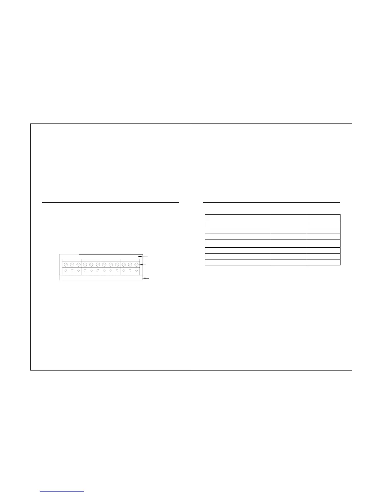
2. Loosen the screws for the appropriate system type selected; see Table 1. See Table 2 for
terminal designation descriptions. Insert wires in the terminal block under the loosened
screw. See Fig. 8.
3. Securely tighten each screw.
4. Push excess wire back into the hole.
5. Plug the hole with nonflammable insulation to prevent drafts from affecting the thermostat.
6. See Fig. 9 through 16 for typical wiring hookups.
Fig. 7. Selecting terminal identifications for system type.
18
CONVENTIONAL
HEAT PUMP
SCREW
TERMINALS
S1 S2 C R RC L
S1 S2 C R RC W Y G
O/B
Y G
STS11 Touchscreen Pro
ype.
System Type
Wallplate Terminal
Identifications
Wiring Diagram
Reference
Standard Heat/Cool Conventional
9, 10
Heat Only Conventional
11
Heat Only with Fan Conventional
12
Heat Only Power to open and power to
close zone valves
Conventional
13
Normally Open Zone Valves Heat Only
Conventional
14
Cool Only Conventional
15
Heat Pump without auxiliary heat Heat Pump
16
19
 Loading...