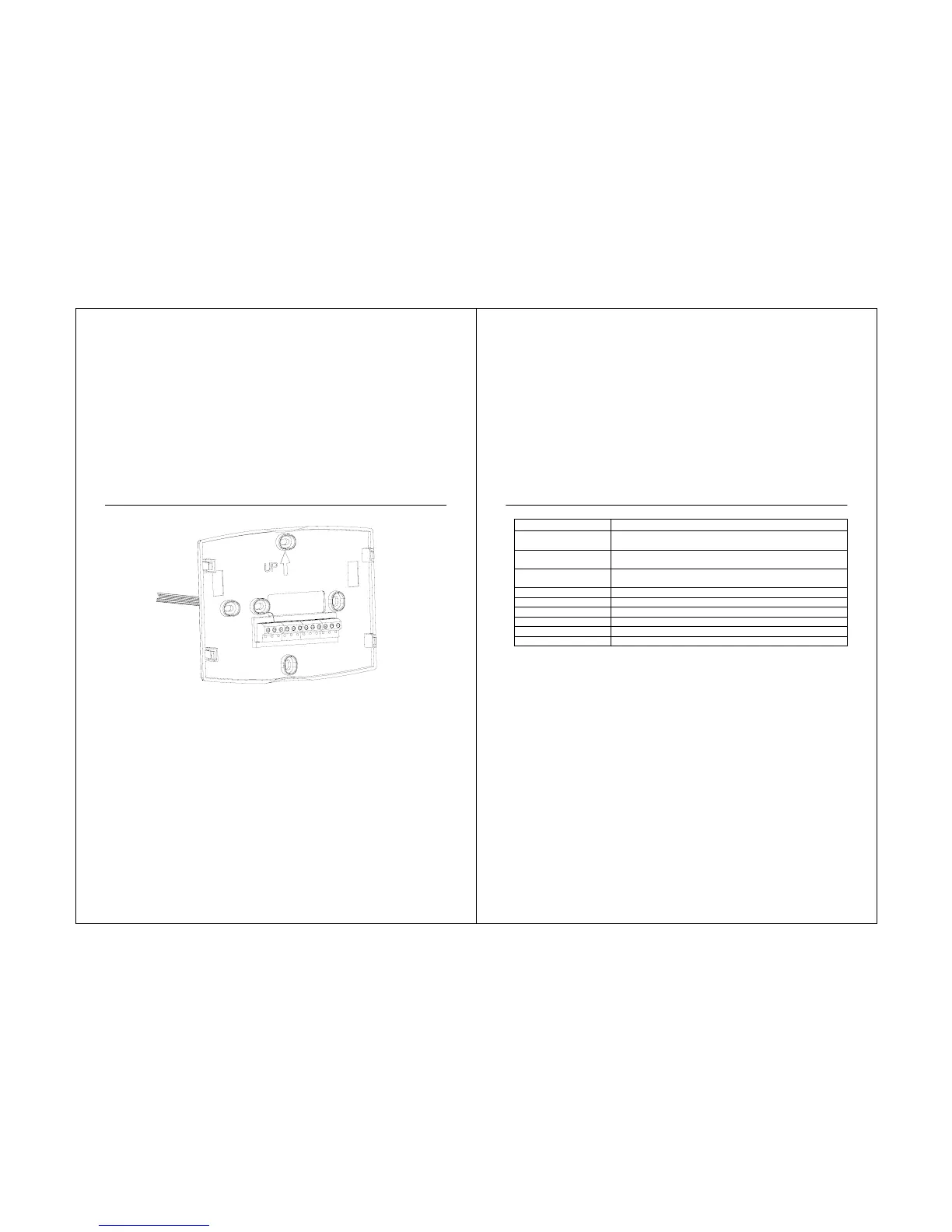
erminal Designation Descriptions.
Terminal Designation Description
RC (see Note 1)
Power for cooling--connect to secondary side of cooling
system transformer
R (see Note 1)
Power for heating--connect to secondary side of heating
system transformer
C (see Note 2)
Common wire from secondary side of cooling system
transformer
W Heat relay
Y Compressor contactor
G Fan relay
O/B (see Note 3) Changeover valve for heat pump system
L (see note 4) Equipment monitor for heat pump system
S1, S2 Optional outdoor or indoor remote sensor
21
NOTES:
1. When used in a single-transformer system, leave metal jumper wire in place between RC
and R. If used on a two-transformer system, remove metal jumper wire between RC and R.
2. Common wire is optional when thermostat is used with batteries.
3. If thermostat is configured for a heat pump system in the Installer Setup, configure
changeover valve for cool (O-factory setting) or heat (B).
4. The “L” terminal is an input (system monitor) when the System mode is in the HEAT, OFF,
COOL or AUTO position. When using the “L” terminal connect the 24 VAC Common. See LCD
indications on page 81.
 Loading...