ADJUSTING THE BYPASS VALVE AND PRESSURE SWITCH
TIP: Bypass adjustment should be performed by a professional technician using a proper gauge and
equipment. Without the proper equipment, you could mis-adjust the valve or switch causing the pump to
work improperly (see Caution below).
About the Bypass Valve
The pump uses a spring-loaded bypass valve to maintain smooth performance as water demands rise
and fall. When a faucet is turned on the pump is providing full water flow, so the bypass valve is closed.
But when there is little to no water demand, the bypass valve opens to allow water to flow back from the
outlet side to the inlet side, keeping a steady flow of water within the pump with almost no cycling.
ADJUSTING THE PUMP'S SHUT-OFF PRESSURE: (1)
@pressureswitch1
SEAFLO
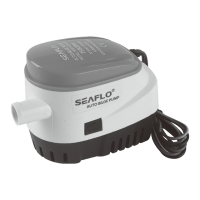
Diaphragm Pump Manual - 55 Series
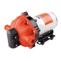
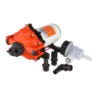
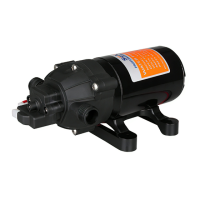
An economical workhorse, the 55 series are engineered for flexibility. The 5 chamber series are our Heavy-Duty
water pump. It provides high volume water flow with reduced pump cycling, thanks to the large five-chamber
diaphragm. With on-demand switch, 3.0 to 5.0 GPM, and 70 PSI, new demand switch, control of pressure precise,
stable performance, low starting pressure, good heat dissipation, the 55 series will meet your special
requirements with positive predictable performance. With built-in bypass function, 55 series is able to reduce rapid
cycling and allow water to flow back from the outside to the inlet side of the pump. SEAFLO also offers a variety of
• To raise the shut-off pressure, use a 2mm Allen wrench to tum
the pressure switch screw clockwise to the desired pressure.
• To lower the shut-off pressure, use a 2mm Allen wrench to turn
the pressure switch screw counter-clockwise to the desired
pressure.
ADJUSTING THE BYPASS: 2
Slide a screwdriver in the removal slot and pry out bypass valve
access hole cover.
Locate the bypass valve adjustment screw on the pump housing
at the bottom of the access hole.
To raise the pressure at which the bypass starts and raise
the full bypass pressure, use a 2mm Allen wrench to turn the
bypass screw clockwise to the desired pressure.
To lower the pressure at which the bypass starts and lower
the full bypass pressure, use a 2mm Allen wrench to turn the
bypass screw counter-clockwise to the desired pressure.
ABOUT THE BYPASS
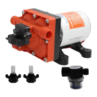
easy connect fittings and filters.
FEATURES
5 chamber diaphragm pump
New demand switch
Industry standard mounting pattern
APPLICATIONS
Run dry capable for normal workloads
Automatic: controlled by pressure switch
Ignition protected
Self priming
Continuous duty
by-pass switch 2
Icture
CAUTION: The pressure setting for full
bypass must be at least 8psi higher than the
shut-off pressure of the pump. If the switch
and bypass is adjusted too closely, the
bypass and switch shut-off can overlap and
the pump will not shut off.
Yacht/RV/caravan pressurized water system
• Sprayer fixtures (vehicle-mounted sprayers, electric sprayers)
• Cleaning machines, humidifier, water purification,
medical apparatus
INSTALLATION
Materials
1 diaphragm pump with related accessories
4 stainless steel hose clamps and screws
4 screws to fasten the pump to the mounting surface
2 (at least) pieces of flexible, reinforced hose piping,
with collapsing strength of twice the inlet collapsing
pressure, hose must be minimum 1/2" ID
• Food beverage filling & liquid transfer
Solar water system
• Any other pressurization system
1 electrical cutoff switch
1 fuse
1 screwdriver
1 strong cutting implement for tubing
(if desired) Teflon tape or sealant
Please consult a professional technician in the case that the bypass needs adjustment. Improper adjustment of
the bypass may damage the pump.
The bypass comes preset for optimal operation of the pump. If your application calls for a different setting for the
bypass, you may change it yourself. Carefully tighten the screw to increase or loosen the screw to decrease the
minimum operational pressure of the bypass.
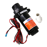
ABOUT NEW SWITCH
We use new demand switch for the pump, it can control of pressure more precise and have good stable
performance.
And low starting pressure, protect the pump start frequently. Good heat dissipation, the switch is directly in contact
with the liquid, so that can serve as a cooling function to prevent the switch from burning out. Also the switch
sealing performance is better.
Please do follow the instruction manual to install the product. Any action outside what is recommended in this
manual may bring damage to the pump. Any inappropriate installation or operation that causes the pump damage
is not covered by warranty.
page
I.The pump may be mounted in any position. If mounted vertically, the pump head should be in the down
position to avoid leakage into the motor casing in the event of a malfunction.
2.Secure the feet, but do not compress them. Over tightening the securing screws may reduce their ability to
dissipate noise and vibration.
3.1ntake hose must be minimum 1/2" (13 mm) ID reinforced hose. Main distribution line from pump outlet should
also be 1/2" (13 mm) ID with branch and individual supply lines to outlets no smaller than 3/8" (10 mm).
4.Plumb the system using high pressure (2x pump rating), braided, flexible tubing to minimize vibration/ noise.
5.Do not apply inlet pressure in excess of 30 psi. In general, try to avoid any inlet pressure completely.
6.Avoid any kinks or fittings which could cause excessive restrictions.
7.Strainer should be attached to the inlet side.
8.The fittings must be secured to avoid leakage.
9.Use clamps at both ends of hose to prevent air leaks into the water line.
10.1f a check valve is installed in the plumbing, it must have a cracking pressure of no more than 2 psi.
11 .lf applying a sealer or plumbing tape, be careful to not overtighten, as they may be sucked into pump.
page