U1
FAULT DETECTION!
The Read/Write LSI (IC SH) continually monitors the + Sand + 12
VOC lines for low voltage conditions. If
+S Volts is > IS% low or
+ 12 Volts is > 20% low, Write Current will be disabled and the
MPU will be reset.
A OC-Unsafe condition will cause a microprocessor reset. This will
prohibit writing. but will not directly cause a WRITE FAULT. If Write
Gate remains true, while the MPU resets from a OC-Unsafe condition,
a WRITE FAULT will be triggered through the loss of READY and
SEEK COMPLETE.
2.2
.050~ ~
I
I
-1L
.CI31UIIII
III· -I~-050
mt:-T II~
; I n t+
I
I
.087
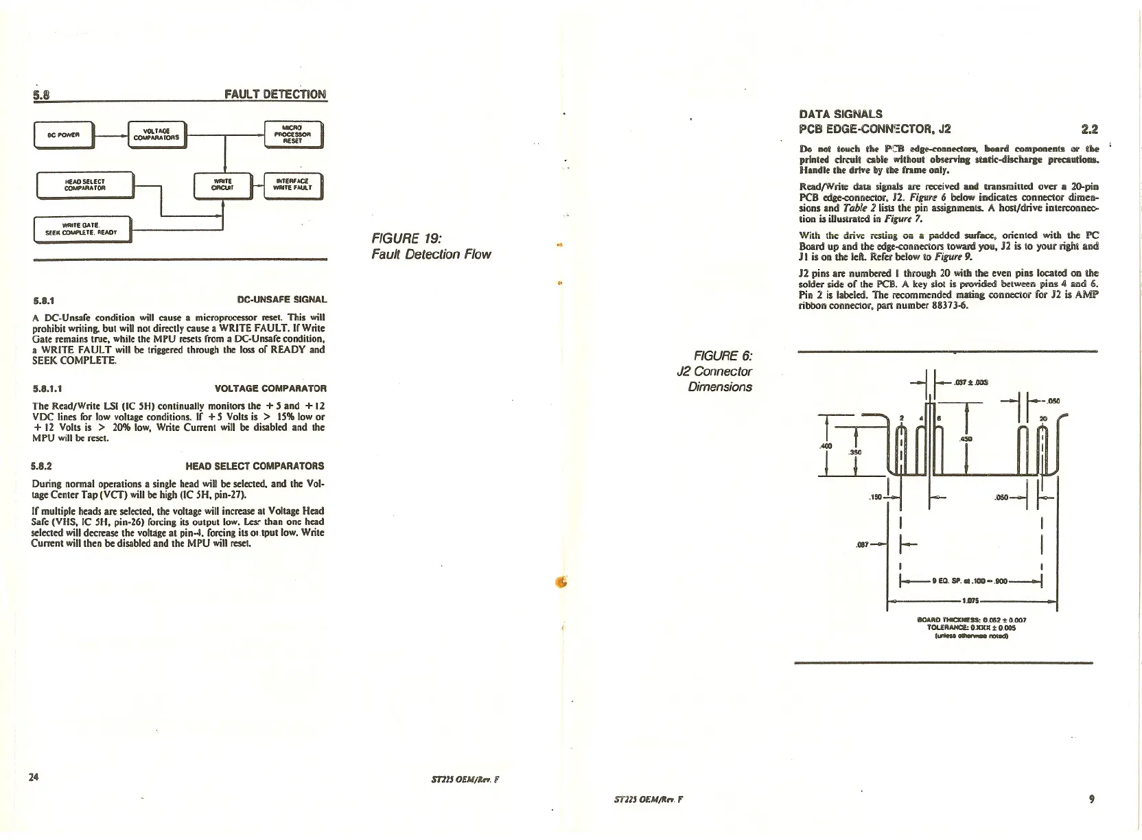
DATA SIGNALS
PCB EDGE-CONN~CTOR, J2
Do not touch the P'-B ~1I~nnectln, Itoani components IIIi' ftbe
printed dmilt alble without observlne ltatlc-dlscharge precautions..
Handle the drl.e by thl2frame only.
ReadfWrite data signals are received ud transmitted over a 20-pin
PCB edge-connector. 12.
Figurlf 6 below indicates connector dimen-
sions and Table 2 lists the pin assignmCIIIs. A host/drive interconnec>-
tion is iUustrated in
Figure 7.
With the driw resting on :I padded surface, oriented with the PC
Board up and the edge-conilectors toward you. J2 is to your right arid
J I is on the left. Refer below to
Figure 9.
J2 pins are numbered I through 20 with the even pins located on the
solder side of the PCB. A key slot is provided between pins 4
Ilnd 6.
Pin 2 is labeled. The recommeilded mating COilnectar for J2 is AMP
ribbon oonilector, part ilumber 88373-6.
FIGURE 6:
J2 Connector
Dimensions
FIGURE 19:
Fault Detection Flow
DC·UNSAFE SIGNAL
VOLTAGE COMPARATOR
HEAD SELECT COMPARATORS
HEAD SELECT
COMPARA TOR
WAeTE QA Tt:.
SEEK COMPl£TE. READY
5.8.1
5.8.1.1
During normal operations a single head will be selected. and the Vol·
\age Center Tap
(vcr) will be high (lC SH, pin-27).
If multiple heads are selected, the voltage will increase at Voltage Head
Safe (VHS. IC SH. pin-26) forcing its output low. Lesr than one head
selected will decrease the voltage at pin-4. forcing its ol.tputlow. Write
Current will then be disabled and the MPU will reset•
5.8.2
e
I I
1---.Ea. SI' .•• ICII~ .100--1
1.1175
IIOA~O YHICKIIESSo 0.082:t 0.007
TOU~AHCI: 0.111111:t 0.005
(
..•..•--
24
mlJ OEM/Itn. F
STllJ OEM/II,.. ,.
9