The control output signals are pted to the interface when sel\:Cted.The
control output signals are DRJVE SELECTED. INDEX. TRACK _.
READY, SEEK COMPLETE and WRJTE FAULT.
DRIVE SELECTED is a status signal transmilled over J2. which in·
forms the host system of the selection status of the drive. The signal is
driven by a TIL open collector. as illustrated in F;gur~ 11. The signal
goes low (true) on the interrace only when the device is configured as
described in Section
J.1. and the appropriate DRJVE SELECT line is
activated by the host system.
Dei
IIOi t01iC1itlte I'(Jj ed~necton, board romponmt. 011' the
printed drcult able without obsenlna siatlc:-dlsc:lwtle precautions.
Handle the tin.it
lily tM frame only.
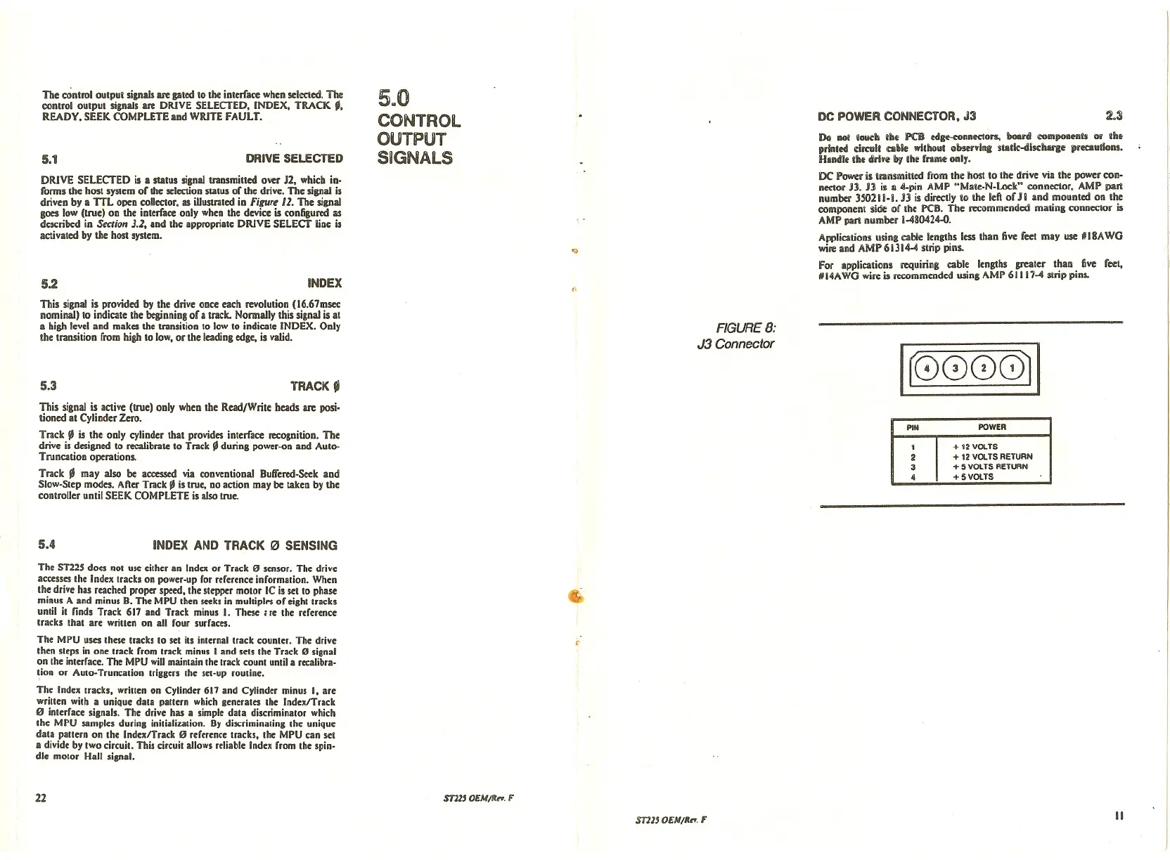
DC POWl:ris transmilted from the host to the drive villithe power con·
nector
JJ. JJ Ii• 4-pin AMP "Male-N-Lock" connector, AMP pan
number 35021 i·l.
JJ is directly to the left of Ji and mounted on the
component side of the PCB. The recommended mating connector is
AMP pari number i-480424.o.
Applications using cable lengths less than live feet may use JIII8AWG
wire and AMP 61314-4 strip pins.
For applications requiring cable lengths grealer than five feel,
JIII4AWGwire is recommended using AMP 61117-4 strip pins.
5.1
5.2
DRIVE SELECTED
INDEX
5wO
CONTROL
OUTPUT
SIGNALS
...
(.
DC POWER CONNECTOR, J3
~.S
This signal is provided by the drive once each revolution (16.67msec
nominal) to indicate the beginning of a track. Normally this signal is at
a high level and makes the transition to low to indicate INDEX. Only
the transition from high to low. or the leading edge. is valid.
5.3
TRACK _
FIGURE 8:
J3 Connector
rr0000il
This signal is active (true) ooly wheo the Read/Write beads are posi.
tioned at Cylinder Zero.
Track ~ is the ooly cylinder that provides interrace recognition. The
drive is designed to recalibrate to Track ~ during power-on aod Auto-
Truncation operations.
Track _ may also be accessed via cooventional Buffered-Seek and
Slow-Step modes. After Track ~ is true, no action may be Iaken by the
controller until SEEK COMPLETE is also true.
PIN
POWER
1
+ 12 VOLTS
2
+ t2 VOLTS RETURN
3
+ 5 VOLTS RETURN
4
+5 VOLTS
5.4
INDEX AND TRACK '" SENSING
The ST22S does oot use eilher an Index or Track" sensor. The drive
accesses the Index Iracks on power-up for reference information. When
the drive has reached proper speed. the stepper motor IC is set to phase
minus A and minus B. The MPU then seeks in multiplrs of eight Iracks
until it finds Track 617 and Track minus I. These He the reference
tracks that are wriuen on all four surfaces.
The MPU uses these Iracks to set hs inlernaltrack counler. The drive
then sleps in one track from Irack minus I and sets the Track" signal
on the interface. The MPU willmainlain Ihe track count until a recalibra-
tion or Auto-Truncation triggers the set-up routine.
The Index tracks, wriuen on Cylinder 617 and Cylinder minus I. are
wriuen wilh a unique data pauern which generates the IndexlTrack
" interface signals. The drive has a simple dala discriminator which
the MPU samples durlns inilializalion. By discriminating Ihe unique
dala paUern on Ihe IndexlTrack '" reference Iracks. Ihe MPU can set
a divide by two circuil. This circuil allows reliable Index from Ihe spin-
dle molor Han sisnal.
22
ST11' OEM/It,.,. F
~
~
ST11' OEM/II,.,. F
II
 Loading...


